


1997 Oct 27 4
Philips Semiconductors Product specification
Vertical deflection power amplifier for
monitors
TDA4860
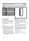
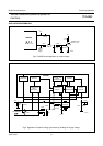
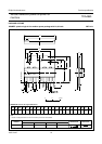
PINNING
SYMBOL PIN DESCRIPTION
V
P1
1 supply voltage 1
INP1 2 input 1 of differential input amplifier
INP2 3 input 2 of differential input amplifier
V
P2
4
supply voltage 2 for vertical output
stage
V-OUT 5 vertical output
SUB 6 substrate
FLB 7 flyback generator output
V
P3
8 flyback supply voltage 3
PCO 9 pulse circuit output
Fig.2 Pin configuration.
handbook, halfpage
TDA4860
MHA593
1
2
3
4
5
6
7
8
9
V
P1
V
P2
V
P3
INP1
INP2
SUB
PCO
FLB
V-OUT
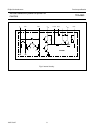
FUNCTIONAL DESCRIPTION
Differential input amplifier
The differential sawtooth input signal (coming from a ramp
output of the TDA4850 for example) is fed to the input
pins 2 and 3. The non-inverted signal is attached to pin 3.
The vertical feedback signal is superimposed on the
inverted input signal on pin 2.
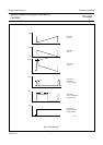
Vertical shift is applied at the inputs in a power-less way
(see Fig.1).
Flyback generator
Signals for the flyback generator and the pulse circuit are
generated in the flyback driver stage. The flyback output
consists of a Darlington transistor and a flyback diode.
The flyback generator can operate in two modes:
1. An external supply voltage is applied for the short
flyback time, thus the power dissipation is minimum
(see Fig.1).
2. The flyback voltage is generated by doubling the
supply voltage (see Fig.5). The 100 µF capacitor C2
between pins 4 and 7 is charged up to V
P1
during
scan, using the external diode and the resistor R2.
The cathode of the capacitor C2 is connected to the
positive rail during flyback. Thus, the flyback voltage is
twice the supply voltage.
Vertical output
The vertical output stage is a quasi-complementary
class-B amplifier with a high linearity. The output contains
SOAR (short-circuit protection) and thermal protection.
The output current on pin 5 is reduced for a short time
(to let the temperature decrease to T
j
< 150 °C), when the
junction temperature (T
j
) exceeds 160 °C.
Deflection GUARD
Pin 9 will go HIGH if the junction temperature goes to high
(see Fig.3). A pulse signal with 50% duty cycle is output on
pin 9, if the deflection coil is open-circuit. A flyback pulse
signal is output at normal conditions.
Further watching can be achieved by means of an external
GUARD circuit as shown in Fig.4. The 22 µF capacitor is
charged during flyback time (V
5
>V
8
) at normal conditions.
In case of failures, the capacitor is discharged and the
GUARD output goes HIGH.
GUARD output level (see Fig.4):
• LOW for normal conditions
• HIGH for deflection coil short-circuit respectively
open-circuit
• HIGH when there are neither input or output signals.