


2003 Feb 12 6
Philips Semiconductors Preliminary specification
70 W high efficiency power amplifier
with diagnostic facility
TDA1562Q; TDA1562ST;
TDA1562SD
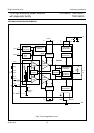
FUNCTIONAL DESCRIPTION
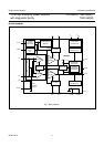
The TDA1562 contains a mono class-H BTL output power
amplifier. At low output power, up to 18 W, the device
operates as a normal BTL amplifier. When a larger output
voltage swing is required, the internal supply voltage is
lifted by means of the external electrolytic capacitors. Due
to this momentarily higher supply voltage the obtainable
output power is 70 W.
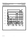
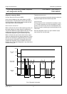
In normal use, when the output is driven with music-like
signals, the high output power is only needed during a
small percentage of time. Under the assumption that a
music signal has a normal (Gaussian) amplitude
distribution, the reduction in dissipation is about 50% when
compared to a class-B output amplifier with the same
output power. The heatsink should be designed for use
with music signals. If the case temperature exceeds
120 °C the device will switch back from class-H to class-B
operation. The high power supply voltage is then disabled
and the output power is limited to 20 W.
When the supply voltage drops below the minimum
operating level, the amplifier will be muted immediately.
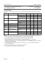
Mode select input (pin MODE)
This pin has 3 modes:
1. LOW for standby: the complete circuit is switched off,
the supply current is very low
2. MID for mute: the circuit is switched on, but the input
signal is suppressed
3. HIGH for on: normal operation, the input signal is
amplified by 26 dB.
When the circuit is switched from mute to on or vice versa
the actual switching takes place at a zero crossing of the
input signal. The circuit contains a quick start option, i.e.
when it is switched directly from standby to on, the
amplifier is fully operational within 50 ms (important for
applications like car telephony and car navigation).
Status I/O (pin STAT)
INPUT
This input has 3 possibilities:
1. LOW for fast mute: the circuit remains switched on, but
the input signal is suppressed
2. MID for class-B: the circuit operates as class-B
amplifier, the high power supply voltage is disabled,
independent of the case temperature
3. HIGH for class-H: the circuit operates as class-H
amplifier, the high power supply voltage is enabled,
independent of the case temperature.
When the circuit is switched from fast mute to class-B/H or
vice versa the switching is immediately carried out. When
the circuit is switched from class-B to class-H or vice versa
the actual switching takes place at a zero crossing of the
input signal.
OUTPUT
This output has 3 possibilities:
1. LOW for mute: acknowledge of muted amplifier
2. MID for class-B: the circuit operates as class-B
amplifier, the high power supply voltage is disabled,
caused by the case temperature T
c
> 120 °C
3. HIGH for class-H: the circuit operates as class-H
amplifier, the high power supply voltage is enabled,
because the case temperature T
c
< 120 °C.
When the circuit is switched from class-B to class-H or vice
versa the actual switching takes place at a zero crossing
of the input signal.
The status I/O pins of maximum 8 devices may be tied
together for synchronizing purposes.