


July 1994 8
Philips Semiconductors Product specification
2 x 6 W hi-fi audio power amplifier TDA1521A
APPLICATION INFORMATION
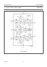
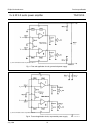
Input mute circuit
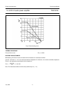
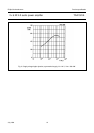
The input mute circuit operates only during switching on and off of the supply voltage. The circuit compares the
1
⁄
2
supply
voltage (at pin 3) with an internally fixed reference voltage (V
ref
), derived directly from the supply voltage. When the
voltage at pin 3 is lower than V
ref
the non-inverting inputs (pins 1 and 9) are disconnected from the amplifier. The voltage
at pin 3 is determined by an internal voltage divider and the external 100 µF capacitor.
During switching on, a time delay is created between the reference voltage and the voltage at pin 3, during which the
input terminal is disconnected, (as illustrated in Fig.3).
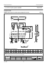
Fig.3 Input mute circuit; time delay.