


July 1994 8
Philips Semiconductors Product specification
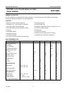
24 W BTL or 2 x 12 watt stereo car radio
power amplifier
TDA1516BQ
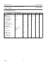
Notes to the characteristics
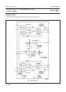
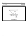
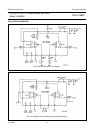
1. All characteristics, for stereo application are measured using the circuit shown in Fig.3.
2. The circuit is d.c. adjusted at V
P
= 6 V to 18 V and a.c. operating at V
P
= 8,5 to 18 V.
3. At 18 V < V
P
< 30 V the d.c. output voltage ≤ V
P
/2.
4. Output power is measured directly at the output pins of the IC.
5. With bootstrap and a 100 kΩ resistor from pin 12 to the positive supply voltage (V
P
), value of bootstrap capacitor is
47 µF.
6. Frequency response externally fixed.
7. Ripple rejection measured at the output with a source impedance of 0 Ω (maximum ripple amplitude of 2 V) and a
frequency between 1 kHz and 10 kHz.
8. Noise voltage measured in a bandwidth of 20 Hz to 20 kHz.
9. Noise output voltage independent of R
S
(V
I
= 0 V).
10. All characteristics, for BTL application are measured using the circuit shown in Fig.4.
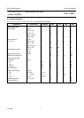
BTL application note 10
Output power THD = 0,5% P
o
15,5 17,0 − W
THD = 10% P
o
20 22 − W
note 5; THD = 10% P
o
21 24 − W
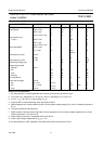
Output power at V
P
= 13,2 V THD = 0,5% P
o
− 13,5 − W
THD = 10% P
o
− 17 − W
note 5; THD = 10% P
o
− 19 − W
Power bandwidth THD = 0,5%
P
o
= 15 W B
w
− 20 to − Hz
15 000
Low frequency roll-off note 6;
−3 dB f
L
− 25 − Hz
High frequency roll-off −1 dB f
H
20 −−kHz
Closed loop voltage gain G
v
25 26 27 dB
Supply voltage ripple
rejection: note 7
ON RR 48 −−dB
mute RR 48 −−dB
stand-by RR 80 −−dB
Input impedance |Z
I
|253038kΩ
Noise output voltage note 8;
ON R
S
= 0 Ω V
no(rms)
− 70 −µV
ON R
S
= 10 kΩ V
no(rms)
− 100 200 µV
mute note 9 V
no(rms)
− 60 −µV
PARAMETER CONDITIONS SYMBOL MIN. TYP. MAX. UNIT