4.3 Cover Removal
WARNING: Removal of the cover should
only be performed by qualified service
personnel--not user serviceable.The unit
should always be unplugged, before removing
the cover and remain unplugged while the
cover is removed.
4.3 Démontage du Couvercle
Le démontage du couvercle et le réglage des
commandes internes doivent être effectués
par du personnel qualifié- pas de service par
l'utilisateur. L'appareil doit toujours être
débranché lorsque l'on retire le couvercle et
doit rester débranché pendant que le
couvercle est ôté.
4.3 Entfernung der Abdeckung
Die Entfernung der Abdeckung und
Hantieren im Innern des Gerätes sollten nur
von qualifiziertem Personal erfolgen. Der
Stecker des Gerätes sollte immer aus der
Steckdose gezogen werden, bevor man die
Abdeckung entfernt, und nicht wieder
hineingesteckt werden, solange die
Abdeckung entfernt ist.
4.3 Desensamble de la Cubierta
Atención: La cubierta ha de ser removida
solo por personal de servicio autorizado -
este equipo no contiene partes que
requieran mantenimiento por usuarios.
Antes de remover la cubierta asegurarse de
que el equipamiento ha sido desconectado
de la alimentación. Esta debe permanecer
desconectada mientras la cubierta este fuera
de lugar.
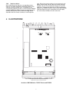
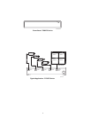
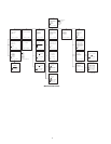
The cover is fastened o the chassis by two screws on the
bottom near the rear of the unit. Disassembly is as shown.
Cover Removal
4.4 Video Inputs
All camera inputs should utilize 2:1 interlaced format
cameras to achieve a real-time update rate (30 frames-per-
second) when used with line-locked cameras that have a
phase error of less than 5 degrees.
4.4.1 TC8275 Series
Connect up to four cameras to the unit. A single BNC
connector, 75 ohm terminated, is provided for each camera
input. See Typical Application - TC8275 Series.
CAUTION:The cover must be removed to
make any DIP switch adjustments. These
settings should only be performed by a
qualified installer or service center. See
Location of DIP Switches under
ILLUSTRATIONS.
4.4.2 TC8277 Series
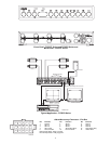
Connect up to four cameras to the unit. See Back Panel -
TC8277 Series under ILLUSTRATIONS. There are
two BNC connectors on the rear panel for each of the four
camera inputs. Use either one of these connectors as a
camera input; the other connector may be used as a looping
output. DIP switch S2 controls the 75 ohm termination for
each of the 4 video inputs. S2 is switched ON for 75 ohm
termination or OFF for nonterminated (looping operation).
The factory default is set for 75 ohm terminated operation.
See Typical Application - TC8278 Series under
ILLUSTRATIONS. Note that a typical application for
TC8277 Series is similar to that for the TC8278 Series.
4.4.3 TC8278 Series
Connect up to eight cameras to the unit. See Typical
Application - TC8278 Series under ILLUSTRATIONS.
There are two BNC connectors on the rear panel for
camera inputs 1 thru 7. Use either one of these connectors
as a camera input; the other connector may be used as a
looping output. Camera input-8 has a single BNC
connector. DIP switches S1 and S2 control the 75 ohm
termination for each of the 8 video inputs. S1 and S2 are
switched ON for 75 ohm termination or OFF for
nonterminated (looping operation). The factory default is
set for 75 ohm terminated operation.
4.5 Monitor Outputs
4.5.1 TC8275 Series
Connect a monitor to the QUAD VIDEO OUT. See
Typical Application - TC8275 Series.
4.5.2 TC8277 Series and TC8278 Series
Connect monitors to MON A and MON B outputs. The
monitor outputs must be terminated in a 75 ohm load. If
the monitor output line is looped through monitors or
other equipment, be sure the monitor terminations are set
to Hi-Z. Only the last unit on the line should have its
termination set to 75 ohm. See Typical Application -
TC8278 Series under ILLUSTRATIONS.
6
Slide Cover Back
Remove Screws From
Bottom Rear Corners
(2) Places
S936A01AE


