


CONTENTS
1 UNPACKING
Unpack carefully.This is electronic equipment and should be
handled carefully.
Check for the following items:
• Model No. of unit.
• One cable with a 15-pin connector on one end. Supplied
only with TC8277 Series and TC8278 Series models.
If an item appears to have been damaged in shipment,
replace it properly in its carton and notify the shipper. If any
items are missing, notify your Philips Communication &
Security Systems Inc. Sales Representative or Customer
Service.
The shipping carton is the safest container in which the unit
may be transported. Save it for possible future use.
2 SERVICE
If the unit ever needs repair service, the customer should
contact the nearest Philips Communication & Security
Systems Inc. Service Center for authorization to return and
shipping instructions.
Service Centers
U.S.A. & Canada: 800-366-2283
Mexico & Central America: 52-5-564-2726
Europe & Middle East: 44-1932-765666
South America: 54-1-956-0837
Australia: 61-2-888-9000
New Zealand: 64-4-237-7297
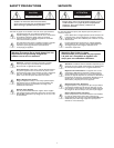
WARNING: Electrostatic-sensitive device. Use
proper CMOS/MOSFET handling precautions to
avoid electrostatic discharge.
NOTE: Grounded wrist straps must be worn and
proper ESD safety precautions observed when
handling the electrostatic-sensitive printed circuit
boards.
3 DESCRIPTION
These video processors digitally capture the full video from
color or monochrome sources, reduces these images to
quarter-screen size, and combines them to provide a
monochrome or color quad display on a single monitor
while retaining all color information.
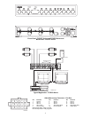
The TC8275 Series has four terminated camera inputs and
one monitor output. A fixed color quad display is provided
on the unit's monitor output, with no on-screen text or
status indications. It has no alarm inputs or other status I/O,
and there are no front panel controls.
The full-featured four channel TC8277 Series and eight
channel TC8278 Series have looping camera inputs and a
VCR input, plus two monitor outputs. Both monitor
outputs have switching capability and both include on-screen
text display capability for camera ID and titles, date and
time, and status indications. Alarm inputs and status I/O is
provided. The TC8277 and TC8278 units are user
programmable via on-screen menus.
The TC8278 eight channel quad displays all eight reduced
images on a single monitor by sequencing two paged color
quad displays.
4 INSTALLATION
4.1 Power
Model Rated Voltage Nominal Power
No.
1
Voltage Range at Rated Voltage
TC8275 120 VAC, 50/60 Hz 108 to 132 15 W
TC8275X 230 VAC, 50/60 Hz 195.5 to 253 15 W
TC8277 120 VAC, 50/60 Hz 108 to 132 15 W
TC8277X 230 VAC, 50/60 Hz 195.5 to 253 15 W
TC8278 120 VAC, 50/60 Hz 108 to 132 15 W
TC8278X 230 VAC, 50/60 Hz 195.5 to 253 15 W
1. The model number and operating voltage are shown on the bottom of
the unit. These units are supplied with grounded power cords;
grounding must not be defeated.
4.2 Mounting
These units are supplied as desk top units. For rack
mounting, the LTC 9101/00 Rack Kit is available. These units
are half-rack units.
5
OBSERVE PRECAUTIONS
FOR HANDLING
ELECTRO STATIC
SENSITIVE DEVICES
ATTENTION
1 UNPACKING . . . . . . . . . . . . . . . . . . . . . . . . . .5
2 SERVICE . . . . . . . . . . . . . . . . . . . . . . . . . . . . .5
3 DESCRIPTION . . . . . . . . . . . . . . . . . . . . . . . .5
4 INSTALLATION . . . . . . . . . . . . . . . . . . . . . . .5
4.1 Power . . . . . . . . . . . . . . . . . . . . . . . . . . . . . . . . . .5
4.2 Mounting . . . . . . . . . . . . . . . . . . . . . . . . . . . . . . . .5
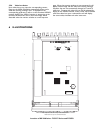
4.3 Cover Removal . . . . . . . . . . . . . . . . . . . . . . . . . . .6
4.3 Démontage du Couvercle . . . . . . . . . . . . . . . . . . .6
4.3 Entfernung der Abdeckung . . . . . . . . . . . . . . . . . . .6
4.3 Desensamble de la Cubierta . . . . . . . . . . . . . . . . .6
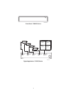
4.4 Video Inputs . . . . . . . . . . . . . . . . . . . . . . . . . . . . .6
4.5 Monitor Outputs . . . . . . . . . . . . . . . . . . . . . . . . . .6
4.6 Alarm Inputs and Output
(Accessory Output) . . . . . . . . . . . . . . . . . . . . . . . .7
4.7 Alarm Inputs . . . . . . . . . . . . . . . . . . . . . . . . . . . . .7
4.8 Alarm Output . . . . . . . . . . . . . . . . . . . . . . . . . . . .7
5 OPERATION . . . . . . . . . . . . . . . . . . . . . . . . . .7
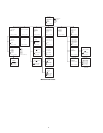
5.1 Menu Operation . . . . . . . . . . . . . . . . . . . . . . . . . .7
5.2 Monitor Operation . . . . . . . . . . . . . . . . . . . . . . . .8
5.3 Alarm Input Operation . . . . . . . . . . . . . . . . . . . .10
6 ILLUSTRATIONS . . . . . . . . . . . . . . . . . . . . . .11