


5
ENGLISH
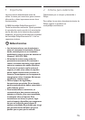
3 Installing your antenna
B Warning
Installation of this product is dangerous. For
your safety, follow the installation directions.
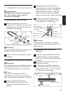
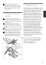
3.1 Mast Clamp Assembly
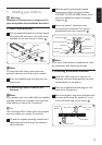
1 Use the supplied hardware to loosely attach
the U-bolt and lock nuts to the mast clamp
assembly on the main boom as shown. 1
U-Bolt
Mast Clamp
Lock Nuts
Backup Plate
Main Boom
1
D Note
To access the mast clamp holes, move the
antenna’s elements out of the way as needed.
2 Press the supplied large end plugs into the
main boom.
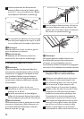
3.2 Connecting Lead-In Cable to the
Antenna
D Note
If you prepare your own cable, slide the supplied
matching transformer’s weather boot onto the
cable before you attach the F-connector.
E Tip
We recommend RG-6 cable, and if you prepare
your own cable, use a quality F-connector.
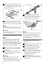
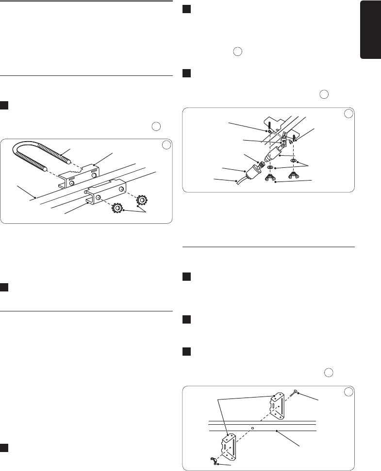
1 Thread the supplied matching transformer’s
spade terminal ends through the antenna’s
strain-relief tab.
2
Slide the spade terminal ends around
the antenna’s lead-in terminals marked
CONNECT LEAD-IN HERE. Secure them
with the supplied at washers and large
wing nuts. 2
3 Screw the cable’s F-connector onto
the matching transformer. Then slip the
weatherboot over the connection.
2
Lead-in
Terminals
Matching Transformer
Flat Washers
Large Wing Nuts
Plastic Strain-Relief Tab
F-Connector
Weather Boot
Coax Cable
Spade Terminal Ends
2
D Note
If you use a cable without a weatherboot, cover
the connection with weatherproof tape.
3.3 Unfolding the Antenna Elements
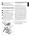
1 Hold each UHF wing boom and turn its
elements until they snap squarely into place
(perpendicular to the boom).
2 Press the supplied small end plugs into the
ends of the wing booms.
3 Bolt the triangular wing boom brackets onto
the main boom using the supplied 1½-inch
screw and small wing nut, as shown. 3
1
1
/
2
Inch
Screw
Main Boom
Small Wing Nut
Wing Boom
Brackets
3