


13
English
Connections
Pb
DIGITAL
OUT
DIGITAL
IN
AUX
IN
TV
IN
LINE
OUT
AUDIO
VIDEO
OUT
CVBS
S-VIDEO
FM ANTENNA
AM
L
R
SPEAKER SYSTEMS
SUB-
WOOFER SURROUND CENTER FRONT
L
R
SL
SUB
SR
C
Pr
Y
AUDIO IN
R L
VIDEO
IN
TO TVINT IN
CH3 CH4
1
4
2
3
P-SCAN
ON OFF
P-SCAN
ON OFF
Pb
DIGITAL
OUT
DIGITAL
IN
AUX
IN
TV
IN
LINE
OUT
AUDIO
VIDEO
OUT
CVBS
S-VIDEO
FM ANTENNA
AM
L
R
WOOFER SURROUND CENTER FRONT
L
R
SL
SUB
SR
C
Y
AUDIO
OUT
Pr/Cr
Pb/Cb
Y
S-VIDEO
IN
VIDEO IN
COMPONENT
VIDEO IN
AUDIO
OUT
Pr/Cr
Pb/Cb
Y
S-VIDEO
IN
VIDEO IN
COMPONENT
VIDEO IN
1
3
Pr
2
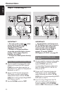
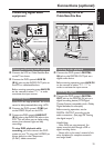
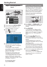
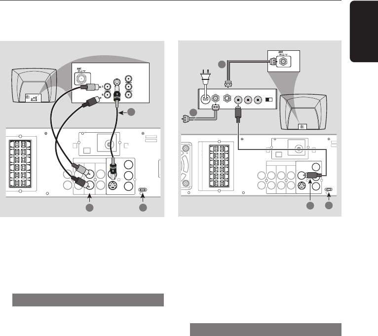
RF coaxial cable to TV
Back of RF Modulator
(example only)
Antenna or
Cable TV signal
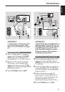
IMPORTANT!
– If the picture is distorted, check
the Video Output setting. Make
sure it is set to ‘S-Video’, see page
29.
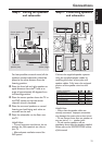
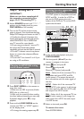
Using S-Video jack
1 Use an S-video cable (not supplied) to
connect the DVD system’s S-VIDEO
OUT jack to the S-Video input jack
(or labeled as Y/C or S-VHS) on the TV.
2 To hear the TV channels through this
DVD system, use the supplied audio
cables (white/red) to connect TV IN
(L/R) jacks to the corresponding AUDIO
OUT jacks on the TV.
3 Set the P-SCAN switch to ‘OFF.’
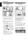
IMPORTANT!
If your TV only has a single Antenna In
jack (labeled as 75 ohm or RF In), you
will need an RF modulator in order to
view DVD playback on the TV. See
your electronics retailer or contact
Philips for details on RF modulator
availability and operations.
Using an accessory RF modulator
1 Use the supplied composite video cable
(yellow) to connect the DVD system’s
CVBS jack to the video input jack on the
RF modulator.
2 Use an RF coaxial cable (not supplied) to
connect ANTENNA OUT or TO TV jack
on the RF modulator to the ANTENNA
IN jack on the TV.
3 Connect the Antenna or Cable TV
service signal to the ANTENNA IN or
RF IN jack on the RF modulator. (It may
have been connected to your TV
previously. Disconnect it from the TV.)
4 Set the P-SCAN switch to ‘OFF.’