


7
EnglishFrançaisDeutschItalianoEspañol
Nederlands
Svenska
Suomi
Polski
Türkçe
Ðóññêèé
NorskDansk
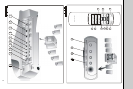
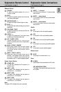
Inputs
1 INPUT 1: 5.1-channel
9 pin DIN jack to connect a 5.1-channel audio-
visual source
2 INPUT 2: stereo channel
3.5 mm stereo jack to connect a stereo audio-
visual source
3 INPUT 3: stereo channel
3.5 mm stereo jack to connect a stereo audio-
visual source
Satellite
4 FRL
To connect the front left satellite speaker
5 FRR
To connect the front right satellite speaker
6 SRL
To connect the surround left satellite speaker
7 SRR
To connect the surround right satellite speaker
8 CTR
To connect the center satellite speaker
Remote Control
9 IR-EYE
To connect the remote control IR-EYE
Power
10 AC-MAIN
Power cable to be connected to the AC outlet
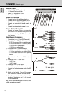
WALL MOUNTING OPTION
The design of the satellites offers wall mounting
as an option
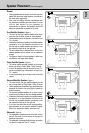
Remote Control
1 STANDBY
To switch the speaker system into ON or OFF
(=STANDBY) mode
2 MUTE
To switch the speaker system into mute mode,
and normal mode again
3 MASTER VOLUME - / +
To adjust the master volume higher or lower
4 BASS - / +
To adjust the bass level according your personal
preference
5 FADE REAR / FRONT
To adjust the loudness of the rear and the front
satellite speakers
6 TREBLE - / +
To adjust the presence of the higher tones
according your personal preference
7 POP / CLASSIC / ROCK
Choose from either the POP, CLASSIC or ROCK
button for optimal pre-set sound reproduction
per genre
8 MOVIE / STEREO / CONCERT
When using a stereo source as input, choose
from either the
MOVIE, STEREO or CONCERT button
for optimal pre-set multi-channel sound
processing
9 INPUT 1 / INPUT 2 / INPUT 3
Make your choice of audio-visual source
selection. Two separate stereo input sources
and one 5.1-channel input source can be
connected to this 5.1-channel speaker system
Remote Control Receiver
10 POWER (LED)
The red color indicates that the system is in
standby mode.
11 INPUT 1 (LED)
The green color indicates that the system is
active and
INPUT 1 is selected
12 INPUT 2 (LED)
The green color indicates that the system is
active and
INPUT 2 is selected
13 INPUT 3 (LED)
The green color indicates that the system is
active and
INPUT 3 is selected
Note:
Two green LEDs indicate that mute is activated.
Explanation Remote Control
( See Illustration A, page 3)
Explanation Cable Connections
( See Illustration B, page 3)