


10
English
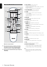
Connecting the speakers
Connect the supplied speaker systems using the supplied
speaker cables by matching the colours of the jacks and
speaker cables.
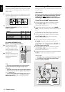
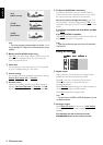
1 Press up (or down) the clip on the speaker’s jack and fully
insert the stripped portion of the speaker cable into the
jack, then release the clip.
8 mm
abc
2 Connect the subwoofer’s AUDIO INPUT jack to the
WOOFER LINE OUT jack and then connect the
speakers as follows :
Speakers
- +
Front Right (R) (FR) black red
Front Left (L) (FL) black white
Centre (C) black green
Surround Right (SR) black grey
Surround Left (SL) black blue
(for model LX8000SA only)
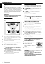
Before connecting the speakers;
● Set up the speaker stands
(refer to the accompanying
“Installation Guide”) or/and
mount the speakers onto the
mini speaker stands as shown in
the illustration.
● Remove the protective cover
only after the connection and
installation of speakers are
completed.
Notes:
– Ensure that the speaker cables are correctly connected.
Improper connections may damage the system due to
short-circuit.
– For optimal sound performance, use the supplied speakers.
– Do not connect more than one speaker to any one pair of
+/- speaker jacks.
– Do not connect speakers with impedance lower than the
speakers supplied. Please refer to the SPECIFICATIONS
section of this manual.
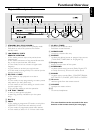
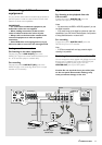
CONNECTIONS
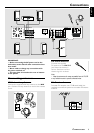
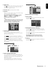
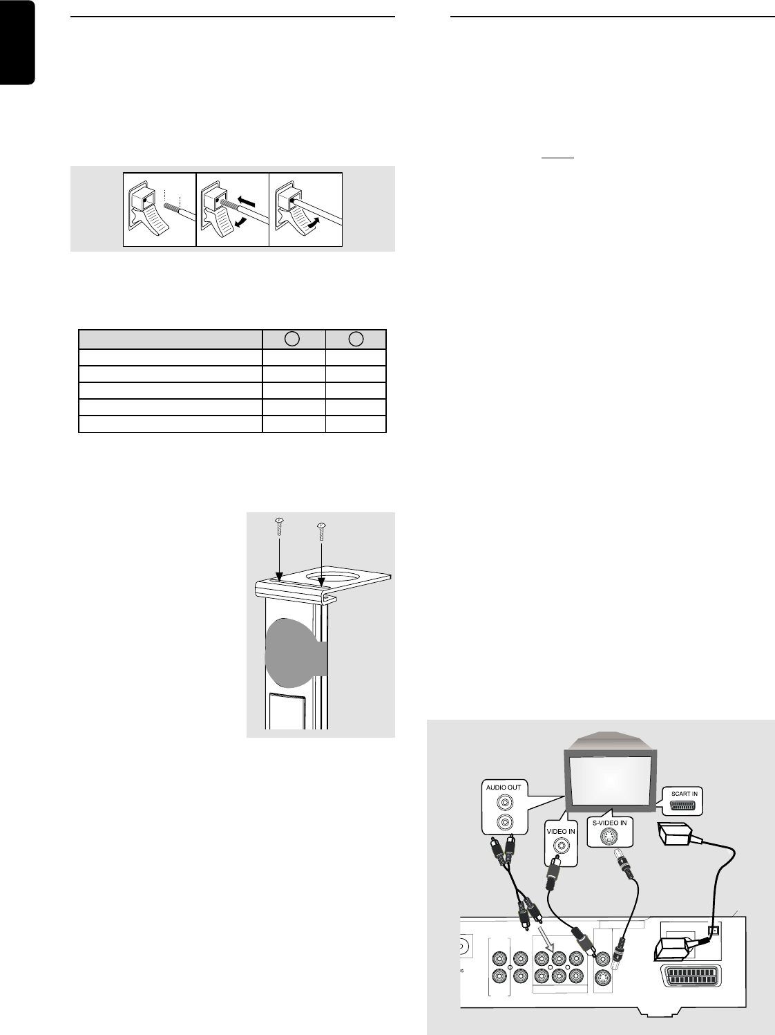
Connecting a TV
You must connect a TV to the DVD system in order to use
the DVD system.
IMPORTANT!
There are various ways to connect the system to a
TV (as shown in the illustration below). You only
need to make ONE of the best connections,
depending on the capabilities of your TV system.
If your TV has a SCART input connector
1 Use the supplied audio cables to connect the system’s
AUDIO-TV IN (L/R) jacks to the corresponding
AUDIO OUT jacks on the TV.
2 Use the Scart cable to connect the system’s SCART
OUT jack to the corresponding SCART VIDEO IN jack on
the TV.
If your TV has a S-Video input connector
1 Use the supplied audio cables to connect the system’s
AUDIO-TV IN (L/R) jacks to the corresponding
AUDIO OUT jacks on the TV.
2 Use the S-Video cable to connect the system’s
S-VIDEO jack to the S-Video input jack on the TV.
If your TV is not equipped with a SCART or
S-Video input connector
1 Use the supplied audio cables to connect the system’s
AUDIO-TV IN (L/R) jacks to the corresponding
AUDIO OUT jacks on the TV.
2 Use the video cable (not supplied) to connect the system’s
CVBS jack to the video input jack on the TV.
Note: On the TV,
– The S-Video In jack may be labeled Y/C, S-Video or S-VHS.
– The CVBS jack is usually yellow and might be labeled
Video In, Composite or Baseband.
+
+
M
W
FM/MW
ANTENNA
FM
75
Ω
SCA
RT O
U
T
S-VIDEO
CVBS
V
ID
EO
O
U
T
A
U
D
IO
AUX
IN
TV
IN
LINE
O
UT
DIG
ITAL
O
UT
CENTER
O
UT
DIGITAL
IN
W
O
O
FER
LINE O
UT
CD
R
1
2
2
2