11
English
A AM Antenna Connection
Connect the supplied loop antenna to the AM AERIAL
terminal. Place the AM loop antenna far away from the
system and adjust its position for the best reception.
B FM Wire Antenna Connection
Connect the supplied FM wire antenna to the FM AERIAL
300 Ω terminal. Adjust the position of the FM antenna
for the best reception.
Outdoor Antenna
For better FM stereo reception connect an outdoor FM
antenna to the FM AERIAL 300 Ω terminal using a 300 Ω
dipole wire.
C Speaker Connections
• Connect the right speaker to Front terminal R, with the
red wire to + and the black wire to -.
• Connect the left speaker to Front terminal L, with the
red wire to + and the
black wire to -.
• Clip the stripped portion
of the speaker wire as
shown.
D Surround Speakers Connection
(for FW386C and FW65C only)
4-Speakers Connection
• Front speakers :
Connect the black wires to the black
FRONT terminals and the red wires to the red FRONT
terminals.
• Rear (surround) speakers :
Connect the black or non-
marked wires to the black REAR terminals and the white
or marked wires to the grey REAR terminals.
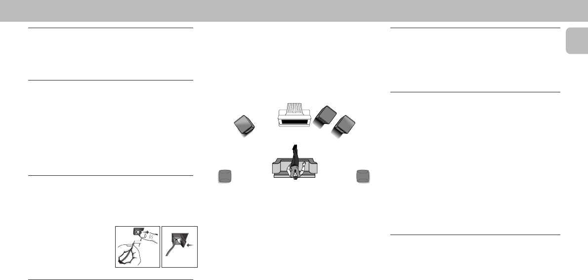
Positioning the Speakers
To get the best surround sound effect, place the speakers
as follow.
TV
SURROUND
RIGHT
SURROUND
LEFT
FRONT
LEFT
FRONT
RIGHT
MINI HIFI
SYSTEM
Front Left and Right Speakers
For best listening effect, it is recommended to have the
Left and Right speakers to form an angle of approximately
45 degrees to the listener. Should the magnetic field from
the speakers affect the picture of the television, you should
increase the separation distance.
Rear (surround) Speakers
The surround speaker should be placed at normal listening
ear level. It can also be mounted on the wall at the back of
the room. Most important , sometimes you need to
experiment creatively when placing the surround speakers
in order to obtain the most ideal sound projection.
PREPARATION
E Connecting other equipment to your
system
You can connect the audio left and right OUT terminals of a
TV, VCR, Laser Disc or DVD player to the AUX IN terminals
at the rear of the system.
F Subwoofer Out Connection
You can connect either an optional active subwoofer or an
optional wireless active subwoofer to the SUBWOOFER
OUT terminal. The wireless system uses a radio frequency
transmitter. The subwoofer reproduces just the low bass
effect (e.g. explosions, the rumble of the spaceships, etc.).
Be sure to follow the instructions supplied with the
subwoofer unit.
Note:
– Availability of wireless transmitter and its peripherals
are subjected to the approval of local authorities. Please
check with respective local safety or approving
authority.
G AC Power Supply
After all other connections have been made, connect the
AC power cord to the system and to the wall outlet.
unlock lock
12 mm


