


Technical data, EASE
™
plots, SoundTubeSPEC
™
software & product downloads available at www.soundtube.com
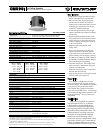
CM590i
In-Ceiling Speaker
Preliminary Technical Information for System Engineers
Data Acquisition
All performance data acquired at
SoundTube’s Technical Measurement
Center (TMC) are analyzed using a
variety of standard measurement tech
-
niques, including Measured Length
Sequence (MLS) and Time Delay Spec
-
trometry (TDS). Performance, develop
-
ment and data acquisition tools include:
Gold Line TEF 20, CLIO, LMS, LEAP, and
proprietary modeling software. EASE
™
data are acquired through an automated
TEF 20/Outline/EASE
™
interface.
EASE™ Data
– 3-D polar plots.
SoundTubeSPEC™
– Proprietary
SoundTube speaker placement software.
Architectural Specifications
The loudspeaker shall consist of a
133 mm (5.25 in) low-frequency trans
-
ducer and a 25 mm (1 in) high-frequency
transducer with a frequency-dividing
network installed in a ported enclosure.
The low-frequency voice coil diameter
shall be 25 mm (1 in).
Performance specifications of a typi
-
cal production unit shall be as follows:
Useable frequency response shall
extend from 69 Hz – 22 kHz (-10 dB,
half space, no external equalization).
Measured sensitivity (2.83 Volt input,
1 meter) shall be at least 90 dB. The
speaker shall have a nominal imped
-
ance of 8 Ohms and shall be available
for 25/70.7/100 Volt modes with voice
coil/8 Ohm direct. The frequency-
dividing network shall have a cross
-
over frequency of 3 kHz with a slope
of 12 dB per octave (second order)
for the high-pass filter. Rated power
capacity shall be at least 80 Watts con
-
tinuous power (RMS), and conforms to
EIA-426-B testing. Maximum continu
-
ous output at 1 meter shall be 109 dB.
The low-frequency transducer shall
have a polypropylene cone with butyl rub
-
ber surround. The high-frequency trans
-
ducer shall be constructed of aluminum
material and incorporate a high-SPL horn
.
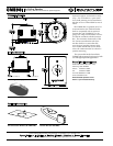
Installation for the CM590i shall be by
2-screw, blind-mount, constant-tension
winged assembly and shall attach to
ceiling thickness tolerances ranging
from 6.4 mm (0.25 in) to 42.9 mm (1.69
in). The fixed-wing assembly shall be
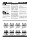
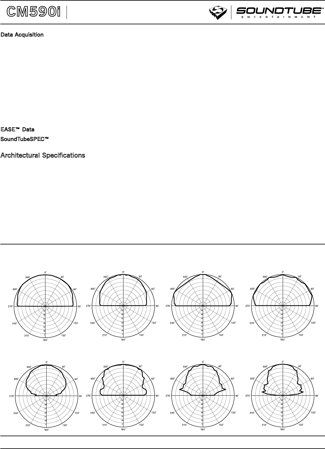
Polar Plots
constructed of glass-filled ABS material.
The external wiring input connector shall
be a 4-pin, 5 mm Euroblock for 8 Ohm or
distributed systems and shall accept from
10 – 22 gauge wire.
The maximum backcan dimensions
shall be no more than 197 mm (7.75 in) in
height by 219.2 mm ( 8.63 in) in diameter.
The maximum visible dimensions shall be
no more than 24.5 mm (0.96 in) in height
by 271.9 mm (10.71 in) in diameter. The
backcan shall be construction of alumi
-
num and affixed to an ABS baffle.
The system shall include a 16-guage
galvanized steel support backing plate
(tile bridge) to reinforce the ceiling mate
-
rial and tile support rails. The maximum
tile bridge dimensions shall be no more
than 600.1 mm (23.61 in) in length by 323.9
mm (12.75 in) in width and 11 mm (0.41 in)
in thickness with a 228.6 mm (9.0 in) diam
-
eter cutout for speaker mounting.
The grille shall be constructed of an ABS
bezel and iridite-plated, powder-coated
steel for lasting performance. The affixed
grille and bezel shall be mounted to the
speaker enclosure (backcan) via neo
-
10,000 Hz
8,000 Hz4,000 Hz
2,000 Hz
1,000 Hz
500 Hz250 Hz
125 Hz