


Right ChannelRight Channel
TECHNOLOGY
CI-6.0 VIII CI-6.1 VIII CI-6.2s VIII CI-7. 2 VIII CI-7. 3 VIII
CI-6.0 VIII CI-6.1 VIII CI-6.2s VIII CI-
CI-6.0 VIII CI-6.1 VIII CI-6.2s VIII CI-7.
2 VIII CI-
2 VIII CI-7.
3 VIII
3 VIII
Install instructions for CI round flush mounts models:
6400 Youngerman Circle | Jacksonville, FL 32244 | (888)phase tk | www.phasetech.com
2. Using the supplied cutout template,
carefully mark the area to be cut out. Using
a drywall knife or saw, cut a hole in the
drywall and prepare the speaker wires for
connection to the speaker terminals.
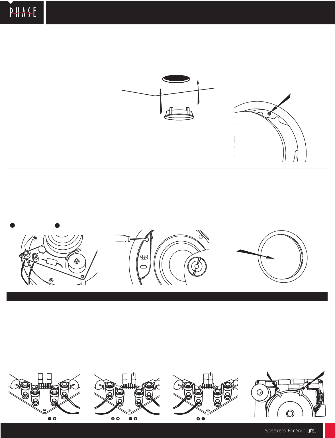
Stereo Point Source FIG.2 – 8 ohms:
Use this configuration to combine left
and right channels for full fidelity sound
from a single loud-speaker stereo source.
Set jumper plugs in the stereo position.
Connect right and left signal wires to the
spring-loaded terminals on the rear of
the speaker.
NOTE –
When deciding upon a location, consider
the following:
• Be certain your speaker wires can be run to or
are accessible from these locations.
• Make certain the wall or ceiling material is
sturdy enough to support the weight and
vibration of the speakers.
• It is recommended that our pre-construction
rough in brackets (part number *RB-17) be used
whenever possible in new construction.
• Be certain the area behind the speaker is free
of obstacles such as wall studs, electrical
wiring, pipes, etc.
• Each speaker should be positioned properly,
relative to the listening area for good coverage.
• Audio performance and room-to-room isolation
will be improved if there is some fiberglass
insulation placed loosely behind the speaker.
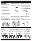
7.
Carefully replace grille by pressing it into
the gap between the flange and the baffle.
Enjoy your new Phase Technology speakers!
5.
Carefully place the
speaker/baffle
in the
flange
making certain that the four V-shaped
index marks on the outer radius of the baffle
and the inside radius of the flange line up.
Attach the
speaker/baffle
to the flange with
the four pre-installed 1” mounting screws on
the baffle.
CAUTION Do not over-tighten.
6. Using some familiar source material,
listen to the tweeter’s balance with the level
control in each of its three positions to find
your favorite.
Wiring options for the CI 6.2s
4. Connect the speaker wires to the
spring-loaded input terminals on the rear of
the speaker, making sure no loose strands
are exposed. If connecting the CI 6.2s
see wiring options below.
Red/positive Black/negative
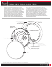
3.
Remove the grille from the mounting
flange by pressing it from behind. Insert the
mounting flange into the hole. Loosen the
flange clamping screws one turn (counter
clockwise) to release the clamp. Next,
tighten all four flange clamp screws evenly
to secure the flange to the wall. It is best to
tighten each screw with the same amount of
force (torque).
CAUTION: Do not over-tighten.
Jumper Plugs
stereo position
Jumper Plugs
stereo position
Mono/Stereo
FIG.3 – 4 ohms: Use
this configuration to drive one channel
(left or right) of a stereo pair with a 4
ohm speaker load. Set jumper plugs in
the mono position. Connect the right or
left signal wire to the left set of posts
on the rear of the speaker. Acoustic
output of the speaker is increased by
3 dB in the configuration.
Bi-pole/Di-pole
FIG.4
–
4 ohms: Use this
configuration for home theater surround
applications. For bi-pole mode, connect
as in the Mono/Stereo
instructions (FIG.3):
one speaker to each surround channel.
For di-pole mode, connect speaker
inputs the same as Mono/Stereo
instructions
(FIG.3), but reverse the + and –
connections of the marked tweeter wires
to put one of the tweeters out of phase.
Left Channel
Left Channel
Stereo
FIG.1 – 8 ohms: Use this
configuration to drive one channel
(left or right) of a stereo pair. Set
jumper plugs in the stereo position.
Connect the right or left signal wire to
the right set of terminals on the rear of
the speaker.
Jumper Plugs
mono position (Bi-pole/di-pole)
1.
Choose the appropriate mounting
location for each speaker.
Flange Installation:
+
–
Speaker Installation:
FIG.1 FIG.2 FIG.3
FIG.4