


MIC/PAGE SWITCH (7)
Selects between mic and page input. The page selection
provides internal pad, converting this input to line level for page
applications.
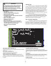
INPUTS (8)
Low Z mic/page inputs are provided via screw terminals. Screw
terminal AUX inputs are paralleled with AUX RCA jacks. (See
AUX IN (5).)
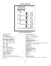
OUTPUTS (9)
A direct output, as well as several transformer outputs, are
provided to allow the proper interface between the amplifier and
the speaker system. The direct output allows direct connection to
a 4 ohms speaker system. Connect the speaker (or speakers)
from the GND terminal to the 4 ohms terminal. For 8 ohms
speaker systems, connect between the COM terminal and the 8
ohms terminal.
25 V and 70 V outputs are also provided for Òconstant volt-
ageÓ speaker distribution systems. The 25 V and 70 V output
connection is between the COM terminal and the 25 V or 70 V
terminal.
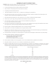
FUSE (10)
The fuse is located within the cap of the fuseholder. It the fuse
should fail, IT MUST BE REPLACED WITH THE SAME TYPE
AND VALUE IN ORDER TO AVOID DAMAGE TO
THE EQUIPMENT AND TO PREVENT VOIDING THE
WARRANTY. If the amp repeatedly blows fuses, it should
be taken to a qualified service center for repair.
WARNING: THE FUSE SHOULD ONLY BE REPLACED
WHEN THE POWER CORD HAS BEEN DISCONNECTED
FROM ITS POWER SOURCE.
AC LINE CORD SOCKET (11)
Provided to accept the removable AC line cord. Connect only to
proper source--see back panel markings.
POWER SWITCH (12)
Used to turn AC mains power on or off.
3
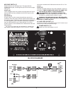
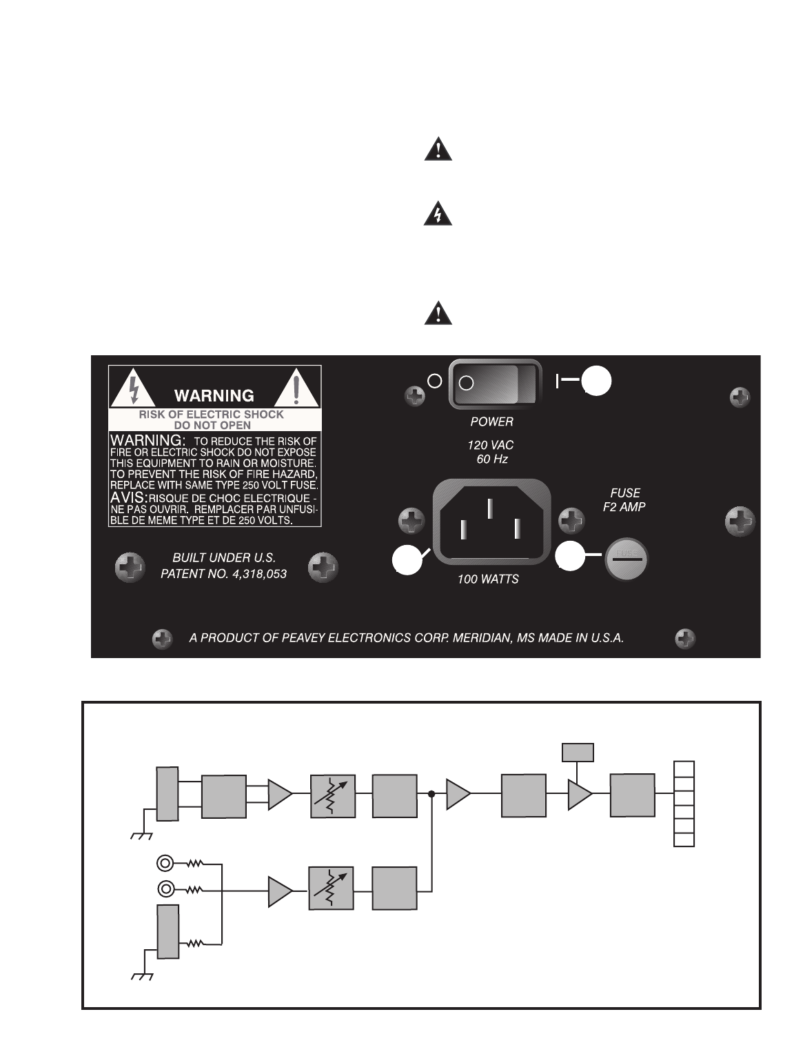
BLOCK DIAGRAM
Level
Level
Muting
Sense
EQ
AMP
Sum
Mic/Page
Selector
Switch
Mic/Page
Barrier
Strip
Aux 1
Barrier
Strip
Transformer
Barrier
Strip
GND
4W
COM
8W
25V
70V
DDT
11
10
12