


10
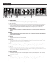
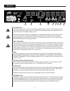
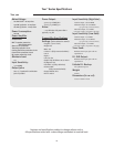
AC POWER INLET:
This is the receptacle for an IEC line cord, which provides AC power to the unit. Connect the line cord to
this connector to provide power to the unit. Damage to the equipment may result if improper line volt-
age is used. (See line voltage marking on unit).
Never break off the ground pin on any equipment. It is provided for your safety. If the outlet used does
not have a ground pin, a suitable grounding adapter should be used, and the third wire should be
grounded properly. To prevent the risk of shock or re hazard, always make sure that the amplier and
all associated equipment is properly grounded.
NOTE: FOR UK ONLY
As the colors of the wires in the mains lead of this apparatus may not correspond with the colored mark-
ings identifying the terminals in your plug, proceed as follows: (1) The wire that is colored green and yel-
low must be connected to the terminal that is marked by the letter E, or by the Earth symbol, or colored
green or green and yellow. (2) The wire that is colored blue must be connected to the terminal that is
marked with the letter N, or the color black. (3) The wire that is colored brown must be connected to the
terminal that is marked with the letter L, or the color red.
FUSE
The fuse is located within the cap of the fuse holder. If the fuse fails, THE FUSE MUST BE REPLACED
WITH THE SAME TYPE AND VALUE IN ORDER TO AVOID DAMAGE TO THE EQUIPMENT AND TO PREVENT
VOIDING THE WARRANTY. If the amp repeatedly blows the fuse, it should be taken to a qualied service
center for repair..
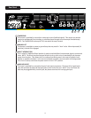
EXTERNAL PARALLELED SPEAKER JACKS
These outputs are provided for connection of external speaker cabinet(s). For connection to virtually
any speaker enclosure, Neutrik Speakon™ 1/4" combination jacks are supplied.
EFFECTS LOOP
The Send Jack provides a pre amp output that may be used to drive slave ampliers and external effects
processors. The Return Jack provides a power amp input for the last effect in the chain. NOTE: When
using the unit as a slave power amplier, the Return Jack should be used as the input.
WARNING: NEVER PLUG THE OUTPUT OF A POWER AMPLIFIER INTO THE RETURN JACK.
FOOTSWITCH JACK
Provided for the connection of the optional footswitch (item #00051000). The Octave Divider may be by-
passed by using this footswitch. When using the footswitch, always insert the plug fully (second click)
into the FOOTSWITCH JACK to ensure proper operation. NOTE: This is a mono type jack. If the tip and
sleeve are shorted while the Octave Divider is in the ACTIVE position, the effect WILL BE muted.
Rear Panel
16
17
19
16
17
23
18
19
20
21
22
24
18
20