


5
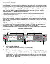
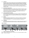
(3) EQUALIZER SECTION
These calibrated, detented controls adjust the amount of cut or boost at their respective
frequencies. They are adjustable from 18 dB cut to 12 dB boost (15 dB cut to 15 dB boost on
the 215B). For units equipped with FLS, the LED at the top of each band will illuminate as an
indication of feedback at that frequency.
(4) LOW-CUT FILTER
This switch activates the low-cut filter that rejects frequencies below 40 Hz. Frequency roll off
is 18 dB per octave with the switch engaged. This filter will operate even with the BYPASS (5)
switch engaged. The adjacent red LED indicates activation.
(5) BYPASS
This switch allows the signal to bypass the unit with the exception of the LOW-CUT FILTER
(4). When this switch is engaged, the signal is routed from INPUT (10 and 11) though the
low-cut filter to output (8 and 9).
(6) POWER
This 2-position rocker switch applies mains power to the unit when in the ON position. The
adjacent green LED indicates mains power activation.
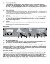
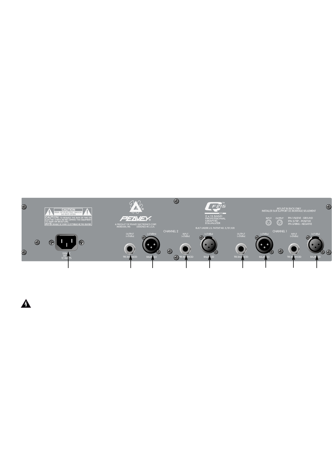
REAR PANEL
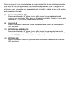
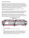
(7) IEC MAINS CONNECTOR
This is a standard IEC power connector. An AC mains cord having the appropriate AC plug
and ratings for the intended operating voltage is included in the carton.
Never break off the ground pin on any equipment. It is provided for your safety. If the outlet used
does not have a ground pin, a suitable grounding adapter should be used and the third wire should
be grounded properly. To prevent the risk of shock or fire hazard, always be sure that the equalizer
and all associated equipment is properly grounded.
NOTE: FOR UK ONLY
If the colors of the wires in the mains lead of this unit do not correspond with the colored markings
identifying the terminals in your plug, proceed as follows: (1) The wire that is colored green and
yellow must be connected to the terminal that is marked by the letter E, the earth symbol, colored
green, or colored green and yellow. (2) The wire that is colored blue must be connected to the
terminal that is marked with the letter N or the color black. (3) The wire that is colored brown must
be connected to the terminal that lis marked with the letter L or the color red.
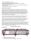
789 10 11
8
9 10
11