


10
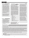
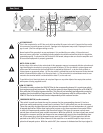
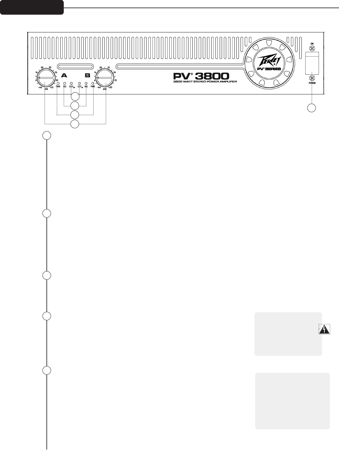
AC POWER SWITCH/CIRCUIT BREAKER
The PV® 3800 amplifier has a combination AC switch/circuit breaker on the front panel. If the switch shuts
off during normal use, push it back to the ON position once. If it will not stay on, the amplifier needs
servicing.
INDICATORS
The PV 3800 amplifier features three front panel LED indicators per channel: DDT™, SIGNAL and POWER.
These LED indicators inform the user of each channel’s operating status and warn of possible abnormal
conditions.
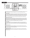
DDT (DISTORTION DETECTION TECHNIQUE) LED
A channel’s DDT LED will light at the onset of clipping. If the LEDs are flashing quickly and intermit-
tently, the channel is just at the clip threshold. A steady, bright glow means the amp is clip limiting,
or reducing gain to prevent severely clipped waveforms from reaching the loudspeakers. See the
Distortion Detection Technique section for more information. During initial power-up the DDT LED
will light to indicate that the RAMPUP™ gain reduction circuitry is activated. This prevents sudden
signal bursts when the speaker relays are closed.
SIGNAL LED
This LED lights when its channel produces an output signal of about 4 volts RMS or more (0.1 volt or more
at the input, with 0 dB attenuation and standard x40 voltage gain). This signal indicates whether a signal
is reaching and being amplified by the amplifier.
POWER LED
The Power LED indicates that its channel’s output relay is closed and the
channel is operational. It lights under normal operation and remains on, even
when the channel is in Distortion Detection Technique or DDT gain reduction.
These protection features leave the output relay closed. If the Power LED
goes off, there is no signal at the output connectors.
INPUT ATTENUATORS
Whenever possible, set the attenuators fully clockwise to maintain optimum
system headroom. The input attenuator controls, located at the front panel
(one for channel A, one for channel B), adjust gain for their respective ampli-
fier channels in all modes. See the specifications at the end of this manual for
standard voltage gain and input sensitivity information.
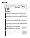
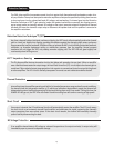
Front Panel
1
2
3
4
5
2
3
4
5
1
The power only breaks
one side of the AC mains.
Hazardous energy may be
present in the enclosure
when the power switch is in
the OFF position.
a
When operating in the Bridged
Mode, both attenuators must
be in the same position so the
speaker load will be equally
shared between the channels.
See the section on Bridged
Mono operation for more
information and precautions.
a