


8
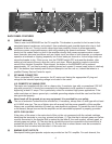
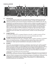
(14) COMBO INPUT CONNECTOR
The combo connector offers both female XLR and 1/4" phone jack balanced inputs for each channel.
The XLR is wired with pin 1 as ground, pin 2 positive input, and pin 3 negative input. The 1/4" phone
jack is a tip/ring/sleeve (3-conductor) type, with the tip being positive input, the ring negative input,
and the sleeve ground. It is important to realize that the XLR, 1/4" jack, and barrier strip inputs are all
in parallel; therefore a balanced input to the associated channel can be accomplished using a male
XLR, a 3-conductor phone jack, or bare wires connected to the barrier strip.
As an alternative, the 1/4" input can also be used with a regular tip/sleeve (2-conductor) type plug
commonly found on single-conductor shielded patch cords. In this case, the input becomes
unbalanced, with the tip as positive input, and the sleeve ground (the ring being grounded by the
sleeve of the plug). An additional unique feature of this 1/4" input jack is something called a “quasi-
balanced” input. The sleeve of this jack is connected to chassis ground through a relatively low-value
resistance that is part of a ground loop elimination circuit. This circuitry will provide hum-free operation
when relatively short 1/4" cable patches are made to this input from various outputs on this amplifier,
or from other equipment that shares the same rack with this amplifier. The quasi-balanced circuitry is
“automatic” and virtually “invisible” in normal usage. This feature can be defeated with a jumper on the
barrier strip from the “-” input terminal of that channel to the ground terminal.
(15) THRU OUT JACKS
The Thru Out is a 1/4" jack supplies signal for patching to additional power amplifier inputs, providing
added flexibility in larger bi-amped systems. This jack is a THRU function, where the output of the
electronically balanced input circuitry is supplied to this jack. The THRU function provides the means
to patch a full range input signal to the other input of this amplifier (for Chan A/B input parallel
mode), or to other amp inputs in the same rack. This function allows one balanced mixer feed to be
connected to the amp via the desired balanced input connector (XLR, 1/4", Barrier), and then further
distributed locally. This 1/4" Thru jack provides an unbalanced (tip/sleeve) output to be patched with
single conductor shielded cables.
INDUSTRIAL AND COMMERCIAL INSTALLATIONS
For commercial and other installations where sustained high-power operation is required, the
amplifiers should be mounted in a standard 19" rack. It is not necessary to leave a rack space
between each amplifier in the stack since each fan pulls air in from the rear and exhausts the hot air
out the front. However, an adequate cool air supply must be provided for the amplifier when rack
mounted. The internal fan must have a source of air that is not preheated by other equipment. The
amplifier will start up in low speed fan operation and will normally stay at low speed unless sustained
high-power operating levels occur. Then, as temperatures in the amplifier heat sinks increase, the
automatic thermal-sensing circuitry will cause high-speed operation to occur. Depending upon signal
conditions and amp loading, high-speed fan operation may continue or the fan may cycle continuously
between high and low. This situation is quite normal. If cooling is inadequate, however, the amplifier
thermal-sensing system may cause temporary shut down of the unit, indicated by the PWR LEDs on
both channels going dark. Inadequate cooling may be due to preheated air, reduced air flow resulting
from blockage of inlet/outlet ports, severe amplifier overload, or short circuit conditions. Depending
upon the available cooling air, operation should be restored relatively quickly, and the power LEDs on
both channels will again be illuminated. In any event, action should be taken to correct the cause of
the thermal shutdown. If the amplifier is not severely overloaded or shorted and air flow is normal in
and out of the amplifier, then steps should be taken to provide a cooler environment for all the
amplifiers. As a general rule, the cooler electronic equipment is operated, the longer its useful service life.
In most low to medium-power applications, the amplifier can be mounted in any configuration. It is
desirable that, if at all possible, the power amplifier be located at the top of an equipment stack. This
will prevent possible overheating of sensitive equipment by the hot air rising from the power amplifier.
As a general rule, most home and studio requirements will never cause high-speed fan operation.
High-speed operation may indicate that you have not taken the necessary steps to provide adequate
cooling. Fully closed up in a cabinet, a PV
®
Series power amplifier will have severe cooling problems,
even at low power levels.