


carefully chosen to allow continuous power output performance while still protecting the power trans-
former. Normally, these breakers should not trip unless there is a fault in the amplifier circuitry that
draws excessive mains current. However, abnormal conditions such as a short circuit on either or both
channels, or continuous operation at overload or clipping (especially into 2 ohm loads) will cause the
breaker to trip. If this occurs, turn the power switch off, then simply reset the breaker and correct the
cause of the overload.
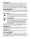
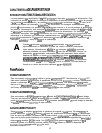
A
When tripped, the button on the breaker will be outward nearly
l/2”
and can be reset
by pushing inward. A normal reset button length is about
l/4”.
If this “thermal” type
breaker does trip, simply pushing the button back in will reset it, after waiting a brief
period of time to allow it to cool down.
REMEMBER,
ALWAYS
TURN
THE
POWER
OFF
BEFORE
RESETTING
THE
BREAKER.
If the breaker trips instantly each time
you attempt to reset it, the unit should be taken to a qualified service center for repair.
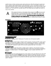
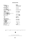
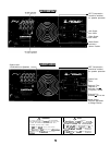
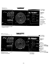
Back Panel
BACK
PANEL FEATURES
POWER SWITCH
(4)
A heavy-duty, rocker-type switch. Selecting the “0” position turns off the power amplifier.
DDT SWITCH
(5)
This switch is used to either Enable or Defeat the DDT compressor. Normally the DDT function should
be enabled to minimize the possibility of either or both channels going into clipping or overload. With
DDT defeated, a severe overload could cause the mains circuit breakers to trip as a matter of course.
(The Peavey DDT compression system will be covered in greater detail later in this manual.)
MODE SWITCH (6)
This switch is used to select either Stereo or Bridge mode of operation. Care should be exercised
whenever the Bridge mode is selected. Accidental selection of this mode could damage loudspeakers,
particularly in biamped systems. (The Bridge mode
will
be covered in greater detail later in this
manual.)
INPUT
GAIN
(7)
These controls are used to adjust the input gain of each channel. Thus, they determine how “loud” each
channel of the power amplifier will
“play”
for a given input signal level. Maximum input gain (minimum
sensitivity rating) is achieved at the full clockwise setting, and this setting yields maximum mixer/system
headroom. A setting of less than full clockwise will yield lower system noise at the expense of mixer/
system headroom.
4