


7
outputs are in parallel and the speaker connection cables can be terminated with banana plugs or
stripped wires for use in the binding post terminals, or can be connected using the Speakon
®
outputs
(9). For sustained high-power applications, either outputs can be used; however, exercise care to
assure the correct speaker phasing. The red binding posts are the signal outputs from each channel,
and the black binding posts are chassis ground. The red binding post should be connected to the
positive inputs of the associated loudspeakers. For BRIDGE mode operation, only the red binding
posts are used and the associated loudspeaker load is connected between the two red posts.
WARNING…Regardless of what connections are used, the minimum parallel speaker load should
always be limited to 4 ohms per channel or 8 ohms BRIDGE mode for any application. Operation at
loads of 4 ohms per channel, or 8 ohms BRIDGE mode, is more desirable for sustained operation
applications because the amplifier will run much cooler at this loading. Operation above 4 ohms per
channel and even open-circuit conditions can always be considered safe, but sustained operation at
loads below 4 ohms could result in temporary amplifier shut down due to the thermal limit circuitry.
(9) SPEAKON
®
OUTPUTS
PV
®
amplifiers utilize three 4-conductor Speakon connectors, one for each channel and one for
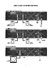
BRIDGE mode. Please refer to the BRIDGE MODE section of this manual before attempting to use
this mode. For each channel Speakon, the same impedance rules apply as with the binding posts.
Internally, all the Speakons are wired in what is called the “high current” mode, with pins 1+ and 2+
in parallel, and pins 1- and 2- in parallel. For the CHANNEL A and CHANNEL B Speakons, the
respective channel output appears on pins 1+ and 2+. Pins 1- and 2- are chassis ground. For the
BRIDGE Speakon, CHANNEL A appears on pins 1+ and 2+, and CHANNEL B appears on pins 1-
and 2-. Always check the Speakon connector wiring carefully before using.
(10) MODE SWITCH
This switch is used to select STEREO or BRIDGE mode operation. It is a conventional push-push
type, requiring a small “tool” to activate. The IN position is BRIDGE mode; the OUT position is
STEREO mode. Exercise care when selecting the BRIDGE mode. Accidental selection of this mode
could damage loudspeakers, particularly in bi-amped systems. Amplifier BRIDGE mode theory will be
covered later in this manual.
(11) DDT
™
(DISTORTION DETECTION TECHNIQUE) SWITCH
This switch is used to enable or defeat the DDT compressor circuitry. It is also a conventional push-
push type, requiring a small “tool” to activate. The IN position is DEFEAT; the OUT position is
ENABLE. Normally, the DDT function should be enabled to minimize the possibility of either or both
channels going into clipping or overload. With this feature defeated, a severe overload could cause
the mains circuit breaker to trip. The Peavey DDT compression system will be covered in greater
detail later in this manual.
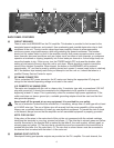
(12) FAN GRILL
A 2-speed DC fan supplies cool air to the amplifier. THIS INTAKE SHOULD NEVER BE BLOCKED!
The fan switches to high speed automatically when the unit requires additional cooling. At idle and
cool, the fan should be in low speed. The fan should never stop unless the amplifier is switched OFF
or the AC mains power source is interrupted.
(13) INPUT BARRIER STRIP
A barrier strip is provided for input connections using bare wire or spade lug connections. PV
amplifiers employ low-noise, electronically balanced input circuitry. This circuitry offers a very wide
dynamic range capable of handling virtually any input signal level, while providing excellent common
mode rejection to minimize hum and reduce interference. This strip accepts balanced and unbalanced
audio signals. The "+" and "-" terminals are the positive and negative inputs to the respective
channels. The GND terminal is the common ground to both channel inputs. For use with an
unbalanced source, connect the "-" input terminal of the channel to ground with a jumper. If the "-"
input is left floating, a 6 dB loss in channel gain will result and the floating input terminal may pick up
outside noise.