


7
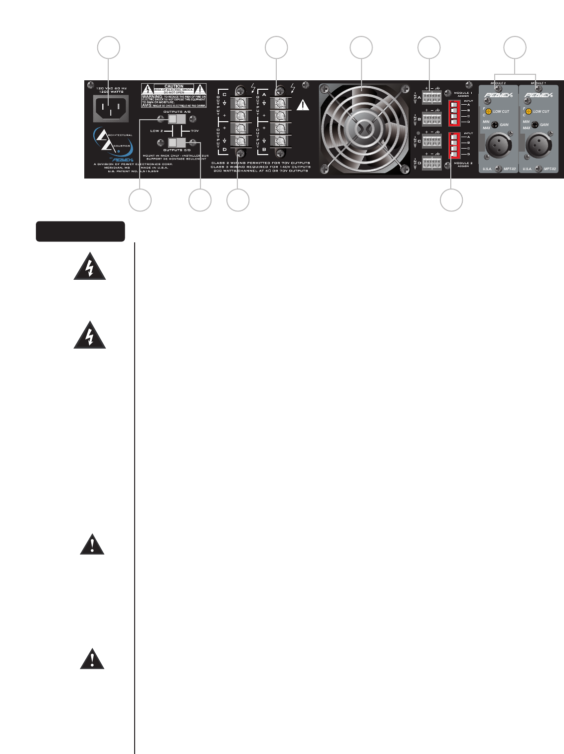
((77)) AACC MMaaiinnss PPoowweerr RReecceeppttaaccllee
This is a standard IEC power connector. An AC mains cord having the appropriate AC plug and ratings
for the intended operating voltage is included in the carton. The mains cord should be connected to
the amplifier before connecting to a suitable AC outlet.
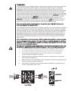
AACC MMaaiinnss CCoorrdd
The mains cord supplied with the unit is heavy-duty‚ 3-conductor type with a conventional 120 VAC
plug with ground pin. Never break off the ground pin on any equipment. It is provided for your safety.
If the outlet used does not have a ground pin‚ a suitable grounding adapter should be used and the
third wire should be properly grounded.
((88)) CChhaannnneell AA//BB OOuuttppuutt SSeelleeccttoorr
(Low Z or 70 Volt)
This slide switch allows channels A and B of this amp to be configured for either conventional Low Z
or to a 70 Volt distribution loudspeaker system.
((99)) CChhaannnneell CC//DD OOuuttppuutt SSeelleeccttoorr
(Low Z or 70 Volt)
This slide switch allows channels C and D of this amp to be configured for either conventional Low Z
or to a 70 Volt distribution loudspeaker system.
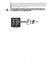
((1100)) CChhaannnneell AA//BB OOuuttppuuttss
The outputs are screw-terminal type for channels A and B. Connect the loudspeaker system to the
respective positive and ground terminals.
((1111)) CChhaannnneell CC//DD OOuuttppuuttss
The outputs are screw-terminal type for channels C and D. Connect the loudspeaker system to the
respective positive and ground terminals.
((1122)) FFaann GGrriillll
A two-speed DC fan supplies cool air to the amplifier. This intake should never be blocked. The fan
automatically switches to high-speed when the unit requires additional cooling. When the amplifier is
relatively cool and at idle‚ the fan should operate at low speed. The fan should never stop unless the
amplifier is switched off or the AC mains power source is interrupted.
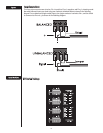
((1133)) CChhaannnneell IInnppuuttss
These removable “Euro” connectors allow for electronically-balanced input signals to be connected to
the system. Each input has a sensitivity of 1.4 V and low-end roll-off at 60 Hz.
((1144)) MMMMAA
™™
PPlluugg--iinn MMoodduullee PPoorrttss
Accepts two optional MMA
™
plug-in input modules. These modules should be selected by installation
requirements. For details‚ refer to the individual MMA Module Operation Guide.
CCaauuttiioonn:: MMMMAA PPlluugg--iinn MMoodduulleess sshhoouulldd nnoott bbee iinnsseerrtteedd oorr rreemmoovveedd wwhhiillee tthhee aammpplliiffiieerr iiss ttuurrnneedd oonn..
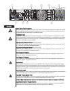
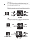
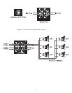
((1155)) MMoodduullee OOuuttppuutt ttoo CChhaannnneell SSeelleeccttoorrss
These DIP switches are used to route the outputs of the respective Module to the desired amplifier
channel(s). For a specific channel selection the DIP switch must be switched.
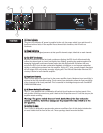
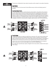
RReeaarr PPaanneell
1234
O
N
1234
O
N
7 10 12 13 14
MODULE 2 MODULE 1
8 9 11 15