


13
The CS
®
800x
4
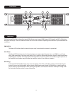
amplifier incorporates several circuits to protect both itself and loudspeakers under virtually any
situation. Peavey has made this amplifier as foolproof as possible by making it immune to short and open circuits,
mismatched loads, DC voltage and overheating. If a channel goes into the DDT™ gain reduction mode, the DDT LED
illuminates. The speaker load remains connected, but clipping percentage or output power is instantly reduced. When
a problem occurs that causes a channel to go into a protection mode, the PWR (Power) LED for that channel will turn
off. DC voltage on the output, excessive subsonic frequencies, or thermal overload will cause the channel’s output
relay to disconnect the speaker load until the problem is corrected or the amplifier cools down.
Distortion Detection Technique (DDT) Limiting
Any time a channel is driven into hard, continuous clipping, the DDT circuit will automatically reduce the channel gain
to a level just slightly into clipping, guarding the speakers against the damaging, high-power, continuous square
waves that may be produced. Situations that may activate the DDT circuit include uncontrolled feedback, oscillations,
an improper equipment setting or malfunction upstream from the amplifier. Normal program transients will not trigger
DDT; only steady, excessive clipping will cause the DDT LED to illuminate.
LFC Impedance Sensing
The CS
800x
4
amplifier features innovative circuitry for safe operation into any load. When an amplifier senses a load
that overstresses the output stage, the Load Fault Correction circuit adjusts the channel gain to a safe level. Extreme
load fault under high power levels will cause the signal to be muted for the associated channel. This method of output
stage protection is far more effective than the standard limiting found on conventional power amplifiers. The LFC
circuit is sonically transparent in normal use and unobtrusive when activated.
Thermal Protection
The internal fan will keep the amplifier operating well within its intended temperature range under all normal
conditions. If the heat sink temperature reaches 85°C, which may indicate an obstructed air supply, the channels will
protect themselves by disconnecting their load and shutting down until the heat sink has cooled. During this time, the
PWR LED will go out, the DDT LED will stay lit and the cooling fan will continue operating at high speed.
Short Circuit
If an output is shorted, the LFC and thermal circuits will automatically protect the amplifier. The LFC circuit senses
the short circuit as an extremely stressful load condition and attenuates the signal, protecting the channel’s output
transistors from over current stress. If the short circuit remains, the amplifier will eventually thermally protect itself by
opening both channel speaker relays, disconnecting the loads until the heat sink cools down.
DC Voltage Protection
If an amplifier channel detects DC voltage or subsonic frequencies at its output terminals, its speaker relay opens and
disconnects the load to prevent speaker damage.
Turn-On/Turn-Off Protection
Upon powering-up, the amplifier mutes the input signals and stays in Protect mode with the speaker connect relays
open for approximately four seconds. This allows the internal power supplies to charge and the amplifier to stabilize.
After the relays engage, the signals slowly increase the muted signals to their normal level. Also, when power is
removed, the input signals are muted so that no thumps or pops are heard.
Protection Features