breaker trips instantly each time you attempt to reset it, the unit should be taken to a qualified
service center for repair.
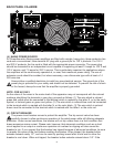
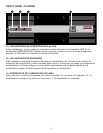
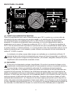
(6) OUTPUT MONITOR
This standard Quick-Connect
ª
RJ11 modular connector provides Channel A and B signals to
PeaveyÕs booth monitor products such as the CA-M400. Refer to the diagram above the connector
for proper polarity. (+ is equal to the channelÕs positive output.) The channels are indicated below the
connector.
(7) BARRIER STRIP SPEAKER OUTPUTS
The SPEAKER OUTPUTS for each channel are provided by means of a heavy-duty, four screw
barrier strip. The screw terminals marked Ò+Ó are the power amplifier outputs for each channel.
The remaining screw terminals are ground (chassis). The minimum recommended speaker load
impedance is 4 ohms per channel, or 8 ohms in BRIDGE mode. Operation into loads below the
recommended load impedance can result in temporary amplifier shutdown due to internal fault
sensing.
(8) SPS SWITCH
This switch is used to either ENABLE or DEFEAT the SPS safety compressor. Normally, the SPS
switch should be in the ENABLE position to minimize the possibility of a channel going into clipping
or overload. With SPS defeated, a severe overload could cause the unitÕs circuit breaker to trip.
(9) MODE SWITCH
This switch is used to select either STEREO or BRIDGE mode for the amplifier operation. Care
should be exercised whenever the BRIDGE mode is selected. Accidental selection of this mode
could cause damage to loudspeakers, particularly in BIAMPED systems. NOTE: Peavey does not
recommend the use of BRIDGE mode for normal theater applications.
(10) INPUT LEVEL
The INPUT controls are labeled in approximately 3 dB increments for ease of gain adjustment.
Maximum input gain is achieved at the full clockwise setting. When used with CinemAcoustics
signal processors, these controls should be left in the full clockwise position.
6


