


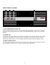
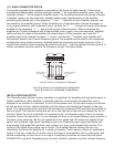
(11) EURO CONNECTOR INPUTS
The popular plugable Euro connector is provided for the inputs for each channel. These inputs
are balanced electronically, with the terminals marked Ò+Ó as the positive amplifier inputs, and the
terminals marked Ò-Ó as the negative amplifier inputs. The remaining terminals are ground (chassis).
If possible, always use two-conductor, shielded cables when interconnecting to the amplifier;
connecting the twisted pair to the respective Ò+Ó and Ò - Ó terminals of each amplifier channel, and
the shields to the amplifier ground. When connecting to a CinemAcoustics Cinema Processor, or
to any signal processor with a balanced output, connect the Ò+Ó, Ò - Ó, and ground inputs of the power
amplifier to the respective Ò+Ó, Ò-Ó, and ground outputs of the processor. When connecting the
amplifier to a Cinema Processor with a single-ended output, again, use a two-conductor, shielded
cable and wire the cable to the amplifier as outlined above. At the processor end, wire the Ò+Ó
amplifier input to the Cinema Processor Ò+Ó output, and wire the Ò-Ó amplifier input together with
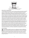
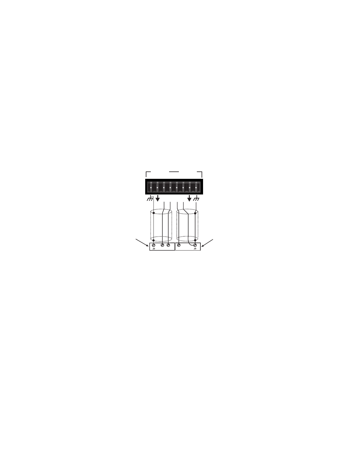
the amplifier shield to the Cinema Processor ground. The amplifier can be wired in an unbalanced
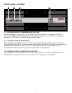
configuration using single-conductor, shielded cables by connecting the single conductor to the Ò+Ó
input of each channel, and connecting the shield to both the Ò-Ó input and ground of each channel. A
similar connection must be made at the Processor as well. See figure below.
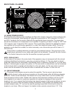
INSTALLATION AND SETUP
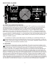
The CinemAcoustics Series of power amplifiers is engineered for durability and high performance in
theater installations. Each amplifier is internally cooled by an automatic two-speed fan, and is
designed to be installed in a standard 19 inch EIA equipment rack. All input and output connections,
as well as level controls, selector switches, and the mains circuit breaker are located on the rear
panel. The mains power switch, and the LED indicators for power and SPS activation are located on
the front panel. The internal cooling fans pull air in from the rear of the unit and exhaust hot air out
the front. When the unit is mounted in an equipment rack, an adequate supply of cool air must be
available. Due to the internal fan, it is not necessary to leave a rack space between each amplifier in
the stack. Upon power-up, the fan will operate at its low speed and will continue to operate at low
speed until sustained, high power operating levels occur. Depending upon signal conditions and
amp loading, high-speed fan operation may continue or it may cycle between high and low. The
cycling of fan speed during active use is normal. The amplifier thermal sensing circuitry may
temporarily shut down the amplifier for a variety of reasons. These reasons include an inadequate
supply of cool air, a reduction of air flow due to blockage of the amplifierÕs inlet or outlet ports, and
severe overloading or short circuit of an output. A temporary shutdown will cause the front panel
POWER LED to go dark. Depending upon the fault condition, operation could be restored relatively
7
++
-- --
++
In
p
ut B is wired in a balanced configuration
Input A is wired in an unbalanced configuration.
Shield
+
-
+
Single-ended output
from processor
Balanced output
from processor
INPUT B
INPUT A
Shield
Input A is wired in an unbalanced configuration.
Input B is wired in a balanced configuration.