


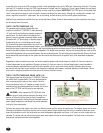

connected to the amp via the XLR connector and then further distributed locally via the THRU jack. Alternatively, when the 1/4" phone
jack input (12) is used as the input, the THRU jack becomes a “bridged” input to it (similar to a Y-cord), again allowing this input signal
to be patched to the other input jack on this amplifier or other amps in the system. IMPORTANT: The THRU jack is not intended to be
“input”, and inadvertent usage as such will result in excessive loading of the input source. Although not a catastrophic mistake, it will
cause a significant reduction in “system gain” due to the loading, and will seriously limit the overall system performance.
Additional input modules are available from your authorized Peavey Dealer. Details of these modules and the installation instructions
can be secured from this source.
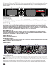
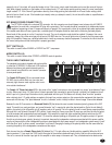
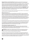
THE P1 OUTPUT MODULE (15)
The standard output module shipped with each
amplifier is called the P1 MODULE. It offers both dual
1/4" jacks and 5-way binding post speaker outputs for
each channel. For each channel, the outputs are in
parallel, hence the speaker connection cables can be
terminated with 1/4" phone plugs, or banana plugs or
stripped wires for use in the binding post terminals.
For sustained high power applications, the use of the
binding post terminals are recommended; however, care must be exercised to assure the correct speaker phasing. The red binding
posts are the signal outputs from each channel, and the black binding posts are chassis ground. The red binding post should be con-
nected to the positive inputs of the associated loudspeakers. For bridge mode operation, only the red binding posts are used, and the
associated loudspeaker load is connected between the two red binding posts. The red binding post associated with Channel A should
be considered the positive output for the system and thus should be connected to the positive input of the associated loudspeaker
system.
Regardless of what connections are used, the minimum parallel speaker load should always be limited to 2 ohms per channel or
4 ohms bridge mode for any application. Operation at loads of 4 ohms per channel or 8 ohms bridge mode is more desirable for
sustained operation applications due to the fact that the amplifier will run much cooler at this loading. Operation above 4 ohms
per channel and even open circuit conditions can always be considered safe; however, sustained operation at loads below 2 ohms
could result in temporary amplifier shut down due to the thermal limits fault circuitry.
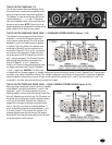
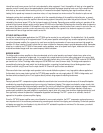
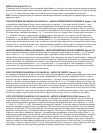
THE P1 OUTPUT MODULE REAR VIEW (16)
This diagram shows the wiring for the P1 MODULE. Note that
the module itself is upside down. This is the desired position
when re-connecting this and any other module. Once the
correct connections to the 1/4" spades are made, then the
module itself can be rotated upward and inserted into the rear
panel of the CS
®
-500A, and the panel screws replaced.
WARNING: Never operate the CS
®
500A with either
the output or input modules removed. Operating in this
manner will allow the air flow from the fans to escape from
these openings instead of flowing through the power amp and
power supply components, and thereby not provide adequate
cooling for these components.
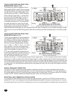
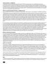
Following are several other module rear views of a different module and the various wiring schemes. The diagram above and the ones
following are provided so that these modules can be correctly wired. Always double-check the wiring. A miswired module can cause
severe audio problems, and in the worst case, can cause loudspeaker degradation and failure. In all cases, the color-coded wires are
indicated. The double red and yellow wires are the power amp outputs and are not interchangeable. The black wires are the power
amp ground connections and are interchangeable.
15
16
6