


CAUTION
PREAMPEFFECTS
OUT
SEND
FUSE
5A
SPEAKER JACKS PARALLELE
D
120W RMS/44V RMS 4 MIN.
BUILT UNDER U.S. PATENT NO. 5,197,102
4 8 16
SPEAKER OUTPUTS
RETURN
SWITCH
60 Hz
400 WATTS
120V
GND.
0
U
S
E
F
F
U
S
E
F
U
S
E
E
S
U
F
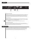
TO REDUCE THE RISK OF FIRE OR ELECTRIC SHOCK, THIS APPARATUS
WARNING:
SHOULD NOT BE EXPOSED TO RAIN OR MOISTURE AND OBJECTS FILLED WITH LIQUIDS,
SUCH AS VASES, SHOULD NOT BE PLACED ON THIS APPARATUS. TO PREVENT THE RISK
AVIS:
ELECTRIQUE, CET APPAREIL NE DOIT PAS ETRE EXPOSE A LA PLUIE OU A L’HUMIDITE ET
AUCUN OBJET REMPLI DE LIQUIDE, TEL QU’UN VASE, NE DOIT ETRE POSE SUR CELUI-CI.
DANS LE BUT DE REDUIRE LES RISQUES D’INCENDIE OU DE DECHARGE
OF FIRE HAZARD, REPLACE WITH SAME TYPE 250 VOLT FUSE.
REMPLACER PAR UNFUSIBLE DE MEME TYPE ET DE 250 VOLTS.
REFER ALL SERVICING TO PEAVEY
AUTHORIZED SERVICE CENTER
CAUTION
ALL TUBES 12AX7A
R
A PRODUCT OF PEAVEY
ELECTRONICS CORP
.
MERIDIAN, MS MADE IN U.S.A.
11
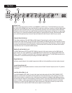
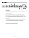
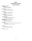
Rear Panel
Remote Footswitch Jack (23)
Provided for the connection of the supplied remote footswitch. When the footswitch is plugged into the
remote footswitch jack, the Channel Select switch [3] must be pressed to the “in” position for remote
selection to operate. Remote selection of the LEAD or RHYTHM channel (left footswitch button) or
outboard devices in the effects loop (right footswitch button) is possible with the remote footswitch.
Speaker Outputs (24)
Paralleled 1/4" output jacks for connecting speaker enclosure(s) to the amplifier (minimum: 4 ohms).
When using more than one enclosure, be sure to calculate the total impedance and set the Impedance
Switch [25] accordingly. (See section on IMPEDANCE SWITCH).
IMPORTANT: Use only high quality, UNshielded cable for speaker connections.
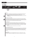
Impedance Selector Switch (25)
Use to select the appropriate impedance of the speaker enclosure(s). If two enclosures of equal
impedance are used, the switch should be set at one half of that value (e.g., for two 16 ohm enclosures,
set switch to 8 ohms; for two 8 ohm enclosures, set switch to 4 ohms).
When connecting the amplifier to the speaker enclosure, make sure to set the impedance selector
switch on the rear of the unit to the impedance that matches your enclosure. When two enclosures
of equal impedance are used, set the switch to one half the impedance of one enclosure (see [25]
Impedance Selector Switch). The 6505 is designed to operate into a minimum of 4 ohms.
23
24
25
Speaker Connection