


4
2
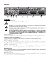
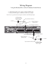
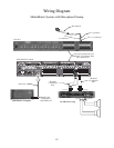
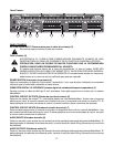
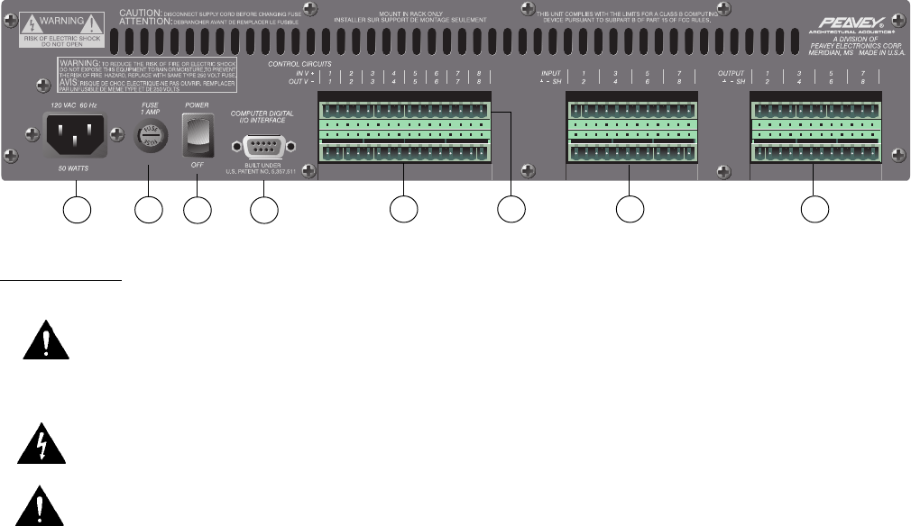
REAR PANEL
IEC LINE CORD INPUT (2)
Provided to accept the removable AC line cord.
FUSE (3)
WARNING: THE FUSE SHOULD ONLY BE REPLACED WHEN THE POWER CORD HAS BEEN
DISCONNECTED FROM ITS POWER SOURCE.
CAUTION: USING A FUSE LARGER THAN THE RECOMMENDED SIZE COULD RESULT IN
PERMANENT DAMAGE TO THE UNIT.
The fuse is located within the cap of the fuseholder. If the fuse should fail, IT MUST BE REPLACED
WITH THE SAME TYPE AND VALUE IN ORDER TO AVOID DAMAGE TO THE EQUIPMENT AND
TO PREVENT VOIDING THE WARRANTY. If the unit repeatedly blows fuses, it should be taken to
a qualified service center for repair.
POWER SWITCH (4)
Switch to “On” position to turn on. The red LED will illuminate indicating power is being supplied to the unit.
COMPUTER DIGITAL I/O INTERFACE (5)
Connect the 9-pin D-type BoB cable here. This cable provides the link to the MediaMatrix system.
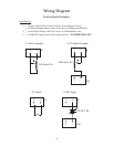
CONTROL CIRCUIT OUTPUTS (6)
These are TTL level outputs, switchable from within a MediaMatrix view. There are two electrical connections
per channel; the right connection is the ground interface and the left connection is the TTL level output. See the
Wiring Connections
section for Control Output circuit examples.
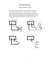
CONTROL CIRCUIT INPUTS (7)
The inputs provide the means of controlling a device within a MediaMatrix view. There are two electrical
connections per channel. See the
Wiring Connections
section for Control Input circuit examples.
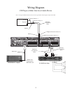
AUDIO INPUTS (8)
Each of these eight channels is a balanced analog audio input to the MediaMatrix system. See the
Wiring
Connections
section for Audio Input wiring examples.
AUDIO OUTPUTS (9)
Each of these eight channels is a balanced analog audio output from the MediaMatrix system. See the
Wiring
Connections
section for Audio Output wiring examples.
Rear Panel:
3
4 5
8
9
6 7