


vide ultra-high performance in a portable,
compact, weather-resistant package. The
enclosure utilizes high-impact polypropy-
lene in an injection-molded plastic trape-
zoidal shape, along with a coated perforat-
ed metal grille to offer a cosmetically ele-
gant yet durable system.
The two-way system includes a 15"
Black Widow
®
woofer with a Kevlar
®
impregnated cone and a specially treated
surround, cone and dust cap for excellent
weather resistance. The RX
™
22 compres-
sion driver features a 2" titanium
diaphragm, a patented phase plug (U.S.
Patent # 6,064,745), and is coupled to an
extremely smooth and well controlled con-
stant directivity horn, with a coverage pat-
tern of 90 degrees by 45 degrees that is
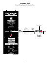
molded into the enclosure. Input connec-
tion to the system is made via 1/4" phone
jacks (2) or 4-pin Neutrik
®
Speakon
®
con-
nectors. Provisions for biamplification are
made through a 4-pin Neutrick switching
jack. The internal passive crossover fea-
tures Sound Guard
™
to protect the tweet-
er, and utilizes high performance compo-
nents and an advanced topology
crossover to provide high power handling
and a smooth yet clear response. The
optimal integration of the crossover with
the selected drivers results in a smooth
frequency response from 60 Hz to 18 kHz.
The free-flow vented cabinet offers
mounting point inserts top and bottom as
well as a molded-in stand adapter for
maximum utility and ease of use.
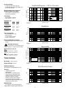
FREQUENCY RESPONSE:
This measurement is useful in deter-
mining how accurately a given unit repro-
duces an input signal. The frequency
response of the Impulse 1015 is mea-
sured at a distance of 1-meter using a 1
watt (into the nominal impedance) swept-
sine input signal. As shown in figure 1, the
selected drivers in the Impulse 1015 8
ohm combine to give a smooth frequency
response from 60Hz - 18 kHz.
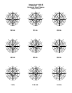
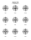
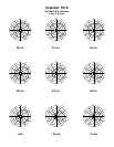
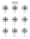
DIRECTIVITY:
Beamwidth is derived from the -6 dB
points from the polar plots (Figure 3)
which are measured in a whole space
anechoic environment. Q and Directivity
Index are plotted for the on-axis measure-
ment position. These are specifications
that provide a reference to the coverage
characteristics of the unit. These parame-
ters provide insight for proper placement
and installation in the chosen environ-
ment. The blending of the components of
the Impulse 1015 8 ohm exhibit a desir-
able beamwidth and directivity (Figure 3
and 4) suitable for sound reinforcement
applications.
3
20 50 100 200 500 1k 2k 5k 10k 20k
Frequency (Hz)
50
60
70
80
90
100
110
120
dB SPL (re 20 Pa)
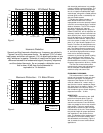
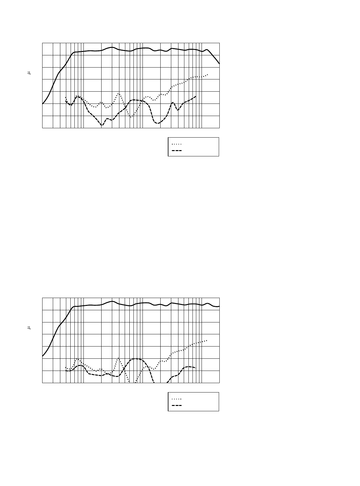
Harmonic Distortion : 10% Rated Power
Figure 5
3rd Harmonic
2nd Harmonic
Harmonic Distortion
Second and third harmonic distortions vs. frequency are plotted in
Figures 5 and 6 for two power levels. Ten percent (10%) of rated
input power and either one percent (1%) of rated input power or one
watt, whichever is greater. Distortion is read from the graph as the
difference between the fundamental signal (frequency response)
and the desired harmonic. As an example, a distortion curve
that is down 40 dB from the fundamental is
equivalent to 1% distortion.
20 50 100 200 500 1k 2k 5k 10k 20k
Frequency (Hz)
40
50
60
70
80
90
100
110
dB SPL (re 20 Pa)
Harmonic Distortion : 1% Rated Power
Figure 6
3rd Harmonic
2nd Harmonic