


8 P/DD-1500 Owner's Manual
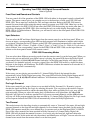
Center Channel Speaker Selector
Set this rear panel switch to accommodate the bass capabilities of your center channel speaker.
Following are descriptions of the recommended center channel switch settings based upon the center
speaker you will be using:
No Speaker, Phantom Mode
Select the No Speaker position if you do not have a center channel speaker. In this position, the front
right and left speakers share reproduction of the mono center channel signal to create a “phantom” image
in the center. In some systems a phantom center channel may provide a wider listening "sweet spot".
Small Speaker, Bass Filter On
Select the Small Speaker position for typical sized center channel speakers. In this position, the P/DD-
1500 protects your center channel speaker from bass overload and distortion by diverting bass
frequencies below 100 Hz to the left and right channels. In this position, front channel imaging remains
tonally balanced even with the limited bass capability of typical smaller center channel loudspeakers.
Large Speaker, Bass Filter Off
Select the Large Speaker position for center channel speakers that have extended low bass capability and
can play as loud as your front left and right speakers without bass distortion. Use this setting for THX
Home Cinema center speakers. In this position, the P/DD-1500 routes the entire audio bandwidth
(20 Hz - 20 kHz) to the center channel output.
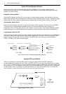
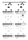
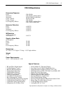
LFE/ Bass Management
Subwoofer On, No Filter
Subwoofer Output = LFE Only
Subwoofer Output On, No Filter
Sub Out = LFE + 5 Channels Mixed
Subwoofer Output Off
LFE & C, LS, RS, Bass Frequencies
Mixed with L, R Channels
LS / RS Channels
Small Speakers
Bass Filter On
Large Speakers
Bass Filter Off
Center Channel Speaker
No Speaker
Phantom Mode
Large Speaker
Bass Filter Off
Small Speaker
Bass Filter On
L C R full range
Sub off
Sub Control
all Modes
L C R Sub
THX Filter
L C R full range
Sub Full Range
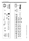
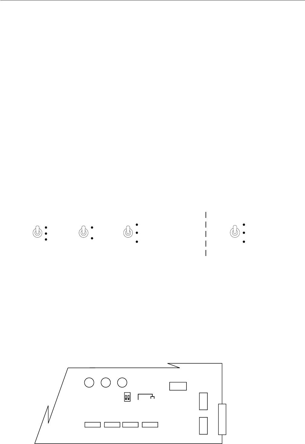
P/DD-1500 and P/SP-1500 Bass Management Switches
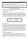
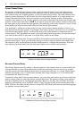
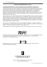
Internal LFE Level Switch
There is an internal two position DIP switch to select the output level of the LFE channel to
accommodate the host processor used with your P/DD-1500. You can select between the factory setting
of 3 V or 5.4 V. During setup, if you are not getting enough output level from the subwoofer channel, set
this position to the 5.4 V position. Conversely, if you discover that the LFE channel is easily overloaded,
set this switch to the 3 V position. To access this switch, you will need to remove the cover panel. Be
sure the power is removed from the wall outlet before you reset this switch.
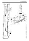
P/DD-1500 P/SP-1500
Rear
of
P/DD-1500
Ri
g
ht Side of P/DD-1500
SW4
1 ON 3V
1 OFF 5.2V
C305
C304
C303
U74
U71
U77
U78
RY6RY5
RY7
1 2
DB-25 Connector