


-2-
Table of Contents
Important Safety Instructions ........................................................................................... 3
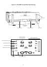
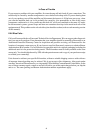
Figure #1 HCA-3500 Front and Rear Panel Drawings ..................................................... 4
Introduction ........................................................................................................................ 5
Ventilation Requirements .................................................................................................. 6
Making Connections to the HCA-3500.............................................................................. 6
RCA Input Connections ..................................................................................................... 6
XLR Input Connections ...................................................................................................... 6
XLR Selector Switch .......................................................................................................... 7
Speaker Connections......................................................................................................... 7
Bi-Wiring ............................................................................................................................. 7
AC Power Connections and AC Grounding ..................................................................... 7
Maintaining Your Parasound Amplifier ............................................................................. 8
In Case of Trouble ............................................................................................................... 8
Special Features for the Parasound HCA-3500 ............................................................... 9
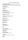
Parasound HCA-3500 Specifications............................................................................. 10
Special Features for the Parasound HCA-3500
Independent power supplies for each channel for true dual-monaural operation
Massive encapsulated 1.4 kVA toroid power transformer for each channel
97,600 uF power supply capacitance for each channel
Multiple polystyrene film bypass capacitors in power supply
Direct coupled design uses no inductors or capacitors in the signal path
DC servo direct-coupled audio circuits with 0.5 Hz rolloff
Output transistors direct-coupled to speakers without LRC networks
Cascode Class A input stages with matched J-FET pairs
Hand-picked complementary MOSFET transistors in high voltage driver stage
High-bias Class A/AB operation provides 15 Watts of pure Class A operation
8 complementary pairs of 15 ampere 60 MHz output transistors per channel
High-quality Neutrik XLR jacks for balanced inputs
Two sets of gold-plated metal structure RCA input jacks for balanced operation
Two sets of gold-plated 5-way binding posts facilitates bi-wiring
Multiple protection circuits, temperature sensors and silver-cadmium relay protection
Glass epoxy circuit boards, double-sided for precision
Two hand-made audiophile-grade AC power cords-separate for each channel