


PARASOUND A 52 DESIGN OVERVIEW
16
Circuit Designed by John Curl
Parasound design consultant John Curl has been a
legend among audiophiles and electronic engineers for
decades. He pioneered measurements to correlate
musical accuracy with the materials used in parts,
worked with world-class touring companies, has
designed highly coveted audio classics, including
the original Mark Levinson JC-2, Denneson JC-80,
Vendetta Phono Preamplifier, and CTC Blowtorch
preamplifiers; master recorders for Wilson Audio and
Mobile Fidelity; and the mixing consoles used in
live concerts by The Grateful Dead and the Montreux
Jazz Festival in Switzerland.
As our featured amplifier designer since 1990, he has
created many products that have earned Parasound
worldwide acclaim. John is particularly proud of what
he and Parasound have accomplished together: “The
circuits I design for Parasound are extremely sophisti-
cated and are typical of products that are far more
expensive. I can’t think of any other audio products
that offer nearly as much bang for the buck.”
Parts Selection
Every part within the A 52 is carefully chosen for its
accuracy and reliability. Metal film resistors with 1%
tolerance are selected for their precision and because
their values don’t drift as they heat up during opera-
tion. Polypropylene and mica capacitors are used
extensively for their superior linearity and low dielec-
tric absorption. Semiconductors are selected for
superior performance in their specific roles in the
circuit. Gold has the best conductivity of any metal,
so we use high quality gold-plated input connectors
and speaker terminals. The double-sided circuit boards
are FR4 glass epoxy for long-term durability. The
chassis is made of heavy gauge steel to safely house
the internal circuitry. This attention to detail when
selecting parts makes the difference between a very
good amplifier and an outstanding amplifier.
The Power Supply
The heart of the power supply is a 1.4 kVA toroidal
power transformer, chosen for its efficiency, low
hum field, and high power rating. Encapsulating this
massive power transformer in an epoxy-filled steel
canister assures ultra-quiet performance.
The A 52 power transformer employs multiple inde-
pendent secondary windings so that each amplifier
channel has its own power supply, assuring more than
ample DC voltage at all times and under all conditions.
It also reduces inter-channel crosstalk that can blur
the sound and impair the correct sense of where
instruments, dialogue and effect are positioned.
Each channel
’s +/- 60 Vdc B+ and B- supply rails use
high-speed rectifier diodes and two large 10,000uF
electrolytic filter capacitors, chosen for their low
Equivalent Series Resistance (ESR) and dielectric
absorption. In addition, these filter capacitors are
bypassed with smaller polypropylene capacitors to
reduce AC ripple in the DC supply and to further
eliminate noise and interference that is generated
in AC power lines from computers and other appli-
ances in the home.
Relay-Bypassed Soft Start Circuit
When the A 52 is first turned on, there is a significant
amount of in-rush current required to charge the enor-
mous power supply capacitors. In order to suppress
this in-rush current and to prevent nuisance tripping
of circuit breakers, we employ NTC (negative tempera-
ture coefficient) resistors. These resistors cut the
in-rush current by approximately 50%. Once they heat
up, they essentially become a jumper with zero ohms
resistance. However, the A 52 goes one step further for
this circuit. After the NTC resistors have done their job
of suppressing in-rush current a gold contact relay auto-
matically is activated to jump across the NTC resistors
to completely bypass them. This extra step insures that
the resistors do not restrict any current whatsoever to
the power supply once the A 52 is in full operation.
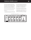
Audio Circuit Path Topology
Parasound’s circuit topology is a hybrid of carefully
chosen discrete transistors that result in superior per-
formance at each stage. We use JFETs (Junction Field
Effect Transistors) for the input stage; MOSFETs
(Metal Oxide Field Effect Transistors) for the driver
stage and bipolar transistors for the output stage.
Discrete transistors are more sonically accurate than
integrated circuits commonly used by other brands.
Complementary Configuration
Each stage of amplification has transistors fed by the
positive DC power supply and complementary transis-
tors fed by the negative DC power supply. Thus, half
of the devices amplify the positive half of the musical
waveform while the other half of the devices amplify
the negative half. This complementary topology is
inherently linear, which reduces distortion and
improves sonic accuracy.
The Input Stage
The A 52’s input stage uses matched pairs of discrete
JFETs arranged in a differential configuration. JFETs
are ideal for the input stage because their inherently
high impedance is unaffected by the impedance of
source components. Differential configuration provides
superior noise reduction. These precision input JFETs
are also cascoded to produce the current necessary
to drive the MOSFET drivers in the following stage.