


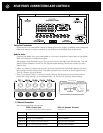
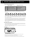


REAR PANEL CONNECTIONS AND CONTROLS continued
When either automatic turn on is selected the Model 5250 v.2 front panel Power button is
disabled so that on/off is determined solely by the triggering preamp or system controller.
Man (Manual) Position
When the Turn On Options switch is in its MAN (manual) position, the Turn On Options function
is disabled and the Model 5250 v.2 must be turned on and off manually by pressing the Power
button on its front panel.
Auto - 12V Position
Your 5250 v.2 will not operate manually when the Turn On Options switch is set to 12V.
When the Turn On Options switch is set to its 12V position, the Model 5250 v.2 is turned on
and off only with an external +9 V to + 12 V voltage from your preamp or controller. When the
external voltage ceases the Model 5250 v.2 will turn off immediately. The 12V switch position
disables the front panel Power button.
Auto - Audio Position
Your 5250 v.2 will not operate manually when the Turn On Options switch is set to Audio.
When the Turn On Options switch is set to its Audio position, the Model 5250 v.2 will be turned
on only when an audio signal is present at its Channels 1 and 2 Input jacks. After the audio
signals cease the Model 5250 v.2 will remain on for about ten minutes before shutting off. This
prevents unintended turn-off during pauses in your music or movies. The Audio position of the
Turn On Options switch also disables the front panel Power button.
Note: When the Turn On Options switch is set to Audio the 5250 v.2 will turn itself on
immediately when you connect its AC cord, even without any audio signal present.
This is normal.
Note: If the Model 5250 v.2 is driving only the sub, surround, center, or rear channels you will
achieve more consistent automatic turn on by using the 12V DC trigger. At the beginning of
most films the sub, center and surround levels are lower than the minimum level required by
the Audio sensing circuit.
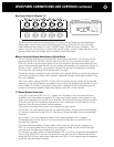
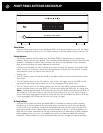
12V In Jack
The Model 5250 v.2 12V input uses a 3.5mm mini jack. To trigger the Model 5250 v.2, insert
the trigger wire plug into this jack and the plug at the wire’s other end into the source compo-
nent’s trigger output jack. We have included a 3.5mm to 3.5mm trigger wire.
Note: Ifthe controller’s trigger output is a + and – terminal, you can cut the 3.5mm plug off one
end of the included trigger wire and attach the bare wires to these terminals. The lead with
the white stripe on it corresponds to the plug’s tip and the unmarked lead corresponds to the
sleeve of the plug.
Note: If the trigger voltage source is DC, the trigger plug tip must be + (positive) and its sleeve
– (negative).
12V Out Jack
The Trigger Out jack lets you loop or “daisy-chain” the incoming trigger voltage to an additional
Model 5250 v.2 or other component
Note: The Model 5250 v.2 trigger circuit draws a negligible 15 mA from the controller. The total
load on your controller’s trigger output(s) is the sum of the trigger current drawn by each of the
components you’ve looped together. Check the maximum capacity of your AV receiver, proces-
sor or home controller’s trigger outputs so you do not overload them by connecting too many
power amplifiers. Typical ratings are 50mA to 100mA.
AC Power Connections and AC Grounding
If possible, plug your Model 5250 v.2 into the same AC outlet that your accompanying audio
components (especially the system controller) are plugged into. The ground potential between
different AC outlets may be different, resulting in audible hum.
7