


8
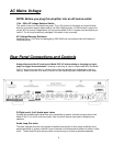
Speaker Connections
Speaker Terminals
There are separate speaker terminals for two pairs of speakers, labeled Speaker Pair A and Speaker
Pair B. The speaker terminals accept speaker wires with banana plugs, spade connectors or bare wire.
Correct Speaker Polarity is Important
Polarity refers to + and – connections. Speaker wires are coded with color, printing or a ridge on the
insulation on one of the leads so you know which lead was connected to the + and – terminals at the
other end. This coding will help you keep the + and - polarity consistent for all channels. If some of the
speakers are wired with incorrect polarity you will significantly affect sound quality.
Speaker Wire Length and Gauge (thickness)
When selecting speaker wire, follow these guidelines:
• Keep the length of your speaker wire as short as possible.
• Use the thickest wire practical. For lengths greater than 50 feet, use speaker wire with an AWG
(gauge) of 14 or lower. The smaller the AWG number, the thicker the wire.
• Do not use speaker wire that is thinner than 16 AWG.
• Keep wire lengths for both channels as close to equal as possible.
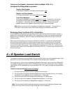
Bridged Mono Operation
Bridged operation configures the Left and Right channels to function as a single higher powered
amplifier channel to drive a single speaker. This is how two Model 2125 v.2 amps are used as
monoblocks to power a pair of speakers. It’s also effective for powering a single passive subwoofer.
Careful attention must be paid to the total impedance of all speakers wired to the unit when it is set for
bridged mono operation. When set to mono the Model 2125 v.2 uses its R channel to amplify only the
positive half of the audio signal and its L channel to amplify only the negative half of the audio signal. In
effect, each channel ―sees‖ only half of the speaker’s rated impedance, so that a single 8 ohm speaker
is actually a 4 ohm load when the amp is bridged to mono. A 4 ohm speaker is a 2 ohm load in bridged
mono. This is why bridged mono power output can be much higher than the sum of the L and R
channel outputs for stereo operation. When the Speaker Load switch is set to the 4-8Ω position the
speaker impedance must be 8 ohms for bridged mono operation. This switch must be set to its 2-3Ω
position if the speaker impedance is less than 8 ohms.
Setting Up the Model 2125 v.2 for Bridged Mono Operation:
1. Turn the unit off and remove the AC cord.
2. Connect the single RCA cable from the preamp or audio controller to the R channel Input jack.
3. Set the Bridged Mono switch to the Bridged (Mono) position.
4. Set the Speaker Load switch to the correct position (see instructions on next page).
5. Connect the positive + lead of the speaker wire to the red R+ channel terminal of speaker pair A.
6. Connect the - negative lead of the speaker wire to the red L+ channel terminal of speaker pair A.
7. Do not connect the L- and R- speaker terminals.
8. If you have a second mono speaker repeat steps 4 - 6 with the speaker pair B terminals.
9. Reconnect the AC cord.
Note: Stereo sound will be faint and distorted if you accidentally leave the Bridging switch in its
Mono position and a stereo pair of speakers are attached.
Note: The Model 2125 v.2 will create more heat when it drives a bridged mono speaker or
multiple speaker pairs. Lower impedance speakers will make it run even hotter. Heat buildup
greatly reduces the life of the amplifier and nearby components. Please pay attention to the
instructions for setting the Speaker Load switch to avoid overheating.