


CONCEPTSYSTEM EXAMPLESCONNECTIONSPRODUCTSBLOCK DIAGRAMS
67
4
PRODUCTS
WU-ZS001E
CONCEPT SYSTEM EXAMPLES CONNECTIONS PRODUCTS BLOCK DIAGRAMS
66
4
PRODUCTS
WU-ZS001E
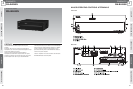
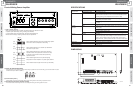
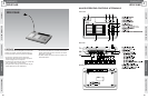
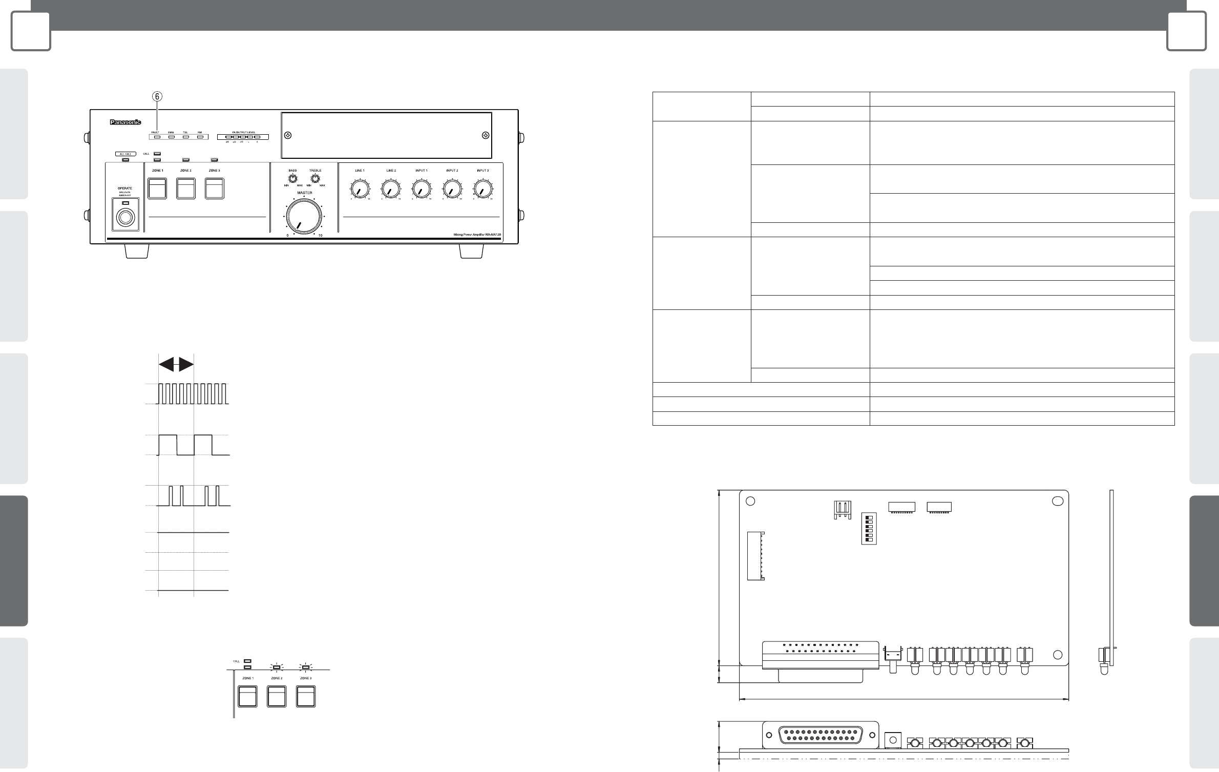
Front of Mixing Power Amplifier
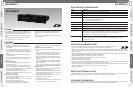
8
6 FAULT Indicator [FAULT]
When this Surveillance Unit is installed, this indicator lights upon detection of a fault.
• Speaker system abnormality (short, grounding, disconnection)
• Power amplifier fault (voice system fault, abnormally high temperature)
Flashes when checking or acquiring reference value for speaker line.
Light
Go out
Light
Go out
Light
Go out
Light
Go out
Light
Go out
1 second
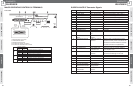
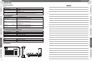
FAULT Indicator flashes 5 times every second during speaker
line check or reference impedance value setting.
FAULT Indicator flashes once a second upon detection of
short circuit or open circuit.
FAULT Indicator flashes twice a second if the reference
impedance value of the speaker line is not set or is faulty.
In this case, set the reference value before performing
speaker line check.
FAULT Indicator lights if there is any abnormally high
temperature in Power Amplifier or any audio signal problems.
FAULT Indicator does not light if there is not any abnormality.
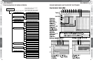
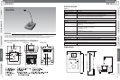
(A) ZONE LED [ZONE1/ZONE2/ ZONE3]
ZONE LED of each zone light during reference value setting or speaker line check. And then they go out one after another in the order
of ZONE number (from ZONE 1 to ZONE 3).
(B) Fault Indicator [FAULT]
FAULT Indicator on the front of the Amplifier flashes quickly during reference value setting or speaker line check.
(C) SETTING STATUS Indicator [SETTING STATUS]
This indicator flashes amber during reference value setting and flashes green during speaker line check .
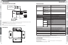
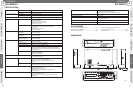
SPECIFICATIONS
DIMENSIONS
150
80153 8
Unit: mm
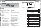
Power
Requirements
Fault Detection
Indicator
Operation
Other I/F
Dimensions
Weight (Approx.)
Ambient Temperature
Rated Voltage
Consumption Current
Line
Amplifier
SW
LED
SW
Parallel
Time Adjustment
24 V DC (supplied internally by amplifier)
Approximately 100 mA
Short (When impedance is -50 % of reference impedance value)
Disconnect (When impedance is +50 % of reference impedance value)
Grounding (When ground impedance value is 50 kΩ or less)
Audio fault (When audio that is greater than the pilot signal level cannot
be detected by the amplifier circuit.)
Abnormally high temperature (When transformer temperature is +100 ˚C
or greater)
Speaker line check trigger/Impedance reference value acquisition trigger
Impedance reference value setting/Speaker line check status indicator
(amber/green)
Line short/disconnect indicator: ZONE 1-3 (red/amber)
GROUND FAULT indicator (red)
Line check trigger/Impedance reference value acquisition trigger
External I/F
Input 2 (Tr input): Open circuit voltage 5 V; Short circuit current 1 mA
Output 17 (open collector output): No-voltage make contact, control
voltage 30 V max., control current 50 mV max. Connector: D-sub 25-pin
Input (Tr input): Open circuit voltage 5 V; Short circuit current 1 mA
150 mm (W) x 18 mm (H) x 88 mm (D)
80 g
0 ˚C to +40 ˚C