


6 7
1
CONCEPT
BASIC SYSTEM DIAGRAM
1
CONCEPT
BASIC SYSTEM DIAGRAM
CONCEPT SYSTEM EXAMPLES CONNECTIONS PRODUCTS BLOCK DIAGRAMS
CONCEPTSYSTEM EXAMPLESCONNECTIONSPRODUCTSBLOCK DIAGRAMS
6 7
WA-MA120N/240N
WA-MA120N/240N
WA-MA120N/240N
WA-MA120N/240N
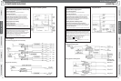
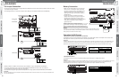
Extension Unit
WU-RM205E
Remote Control
Microphone
WR-210AE
Remote Control
Microphone
WR-210AE
Extension Unit
WU-RM205E
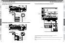
Mixing Power Amplifier
WA-MA120N/240N
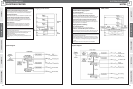
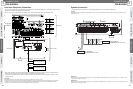
Amplifier (Slave 1)
Amplifier (Master)
Amplifier (Slave 2)
Amplifier (Slave 3)
Amplifier (Slave 4)
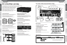
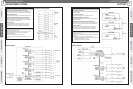
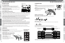
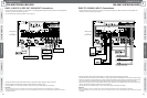
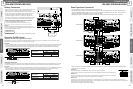
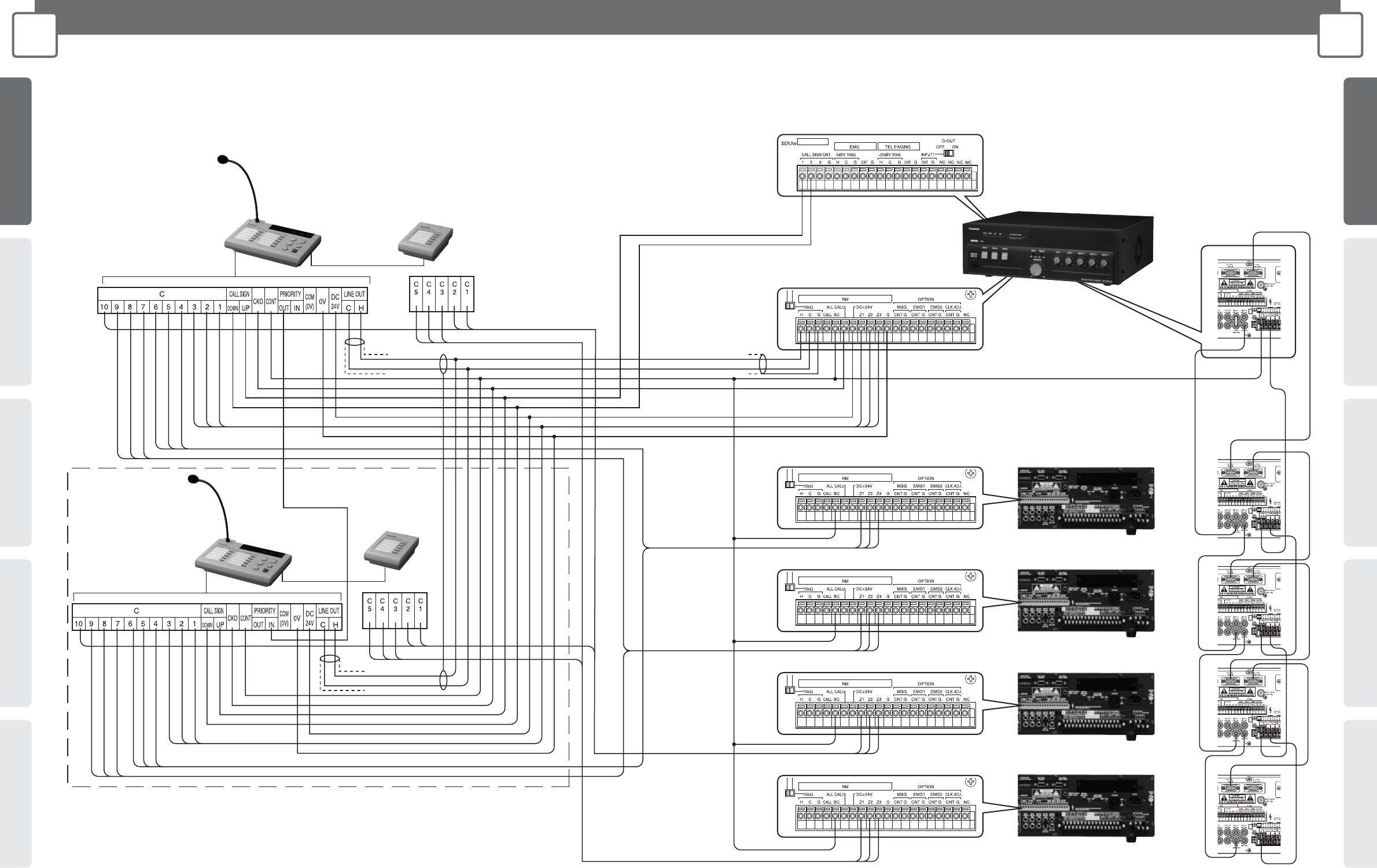
Mixing Power Amplifier (WA-MA120N/240N) Connection
Schematic diagram of Remote Microphone with Extension Unit (WU-RM205E) connected for announcements on 15 channels.
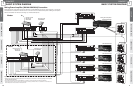
The illustration in the broken line frame shows how to connect more than one Remote Microphones to Mixing Power Amplifier.
Refer to this illustration for method of connecting up to 4 Remote Microphones.
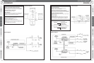
Master
Slave
Important:
• Refer to page 38 and the Operating Instructions for the Amplifier for information on connecting Mixing Power Amplifiers
(WA-MA120N, WA-MA240N).
• Use a crimp connector to group wires together if you need to connect more than one wire to the terminal.
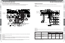
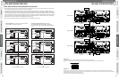
* Announcements can be made on a maximum of 30 channels by connecting 4 Extension Units, for a combination of 10 channels on the
Remote Microphone and 20 channels on the Extension Units.