


4
5
Audio Output LINE OUT 0 dBV, 10 kΩ adapted, unbalanced, RCA pin jack
REC OUT 0 dBV, 10 kΩ adapted, unbalanced, RCA pin jack x 2 (monaural)
INS OUT (Insertion Output) 0 dBV, 10 kΩ adapted, unbalanced, RCA pin jack
INS THRU (Insertion Through Output)
Through output from INS IN, unbalanced, RCA pin jack
INPUT D-OUT (Input Direct Output)
0 dBV, 10 kΩ adapted, unbalanced, RCA pin jack
(Output for 2-channel announcement from INPUT 1 or RM)
Audio In / Out ALL CALL BUS Audio -20 dBV balanced
for Expansion IN / THRU Control Activation control of all-zone announcement
(1) from EMG (2) from TEL / INPUT 1 (3) from RM
Connector 9-pin female D-sub connector x 2 (in / through)
Call Tone Control Input (CALL SIGN CNT) No-voltage make contact input, open voltage : +5 V DC,
(Activation of built-in call tones) short-circuit current : under 1 mA, Push-in terminal*
4
,
1:4-Tone (Up), 2:4-Tone (Down), 3:2-Tone (Down)
One-shot make : single playback, at make : repeat playback
Operation On/Off Control No-voltage make contact input, open voltage : +5 V DC,
(OPERATE ON / OFF) short-circuit current : under 1 mA, M3 screw terminal*
3
Operation Link Control Open collector output, withstand voltage : +30 V DC,
(OPERATE LINK) operating current : under 50 mA, M3 screw terminal*
3
External Attenuator Control In/Out No-voltage make contact output (transfer type relay),
(ATT OVERRIDE) withstand voltage : 30 V DC, 250 V AC, contact current : under 3 A (DC / AC)
M3 screw terminal*
3
Announcement Priority Control Priority 1 : EMG / Priority 2 : TEL PAGING, INPUT 1 / Priority 3 : RM /
(Input Priority at 1-Channel Announcement) Priority 4 : INPUT 2, 3, LINE 1, 2
Priority Indicator EMG, TEL, RM
Level Meter 5 points, -30 / -20 / -15 / -8 / 0
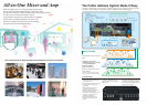
Other Functions • 2-channel announcement by Remote Microphone or paging microphone.
• Zone output extension by connecting plural units. (up to 30 zones by 10 units)
• All-zone announcement in various operating areas. (up to 10 areas)
Phantom Power Supply for INPUT 1-3 +16 V, on / off selectable individually
Power Supply for External Equipment DC +24 V, 0.8 A max., M3 screw terminal*
2
Cooling Fan 3 modes, Stop / Low speed / High speed
Operating Temperature 0 ºC - 45 ºC
Dimensions 420 mm (W) x 146 mm (H) x 404 mm (D)
[Height includes rubber feet and depth includes projections such as rear protect cover.]
Weight (Approx.) 14 kg 15.5 kg
Finish Panel : Gun Metallic painting (ABS Resin)
Case : brack painting, Munsell N1 or equivalent (steel plate)
Accessories AC power cords (x 2), Spare fuses, Rack mounting brackets, Operating instructions
Optional Products • Remote Microphone : WR-210AE / WR-201E
• Booster Power Amplifier : WA-BA240N (240W)
0 dBV = 1 V *1 Can be transformer-balanced with the addition of an optional input transformer.
*2 Barrier distance : 8.12 mm, Suitable cable gauge : AWG 18 ~ 14 (Solid) / AWG 14 (Stranded)
*3 Barrier distance : 6.27 mm, Suitable cable gauge : AWG 22 ~ 14 *4 Suitable cable gauge : AWG 22 ~ 14
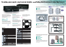
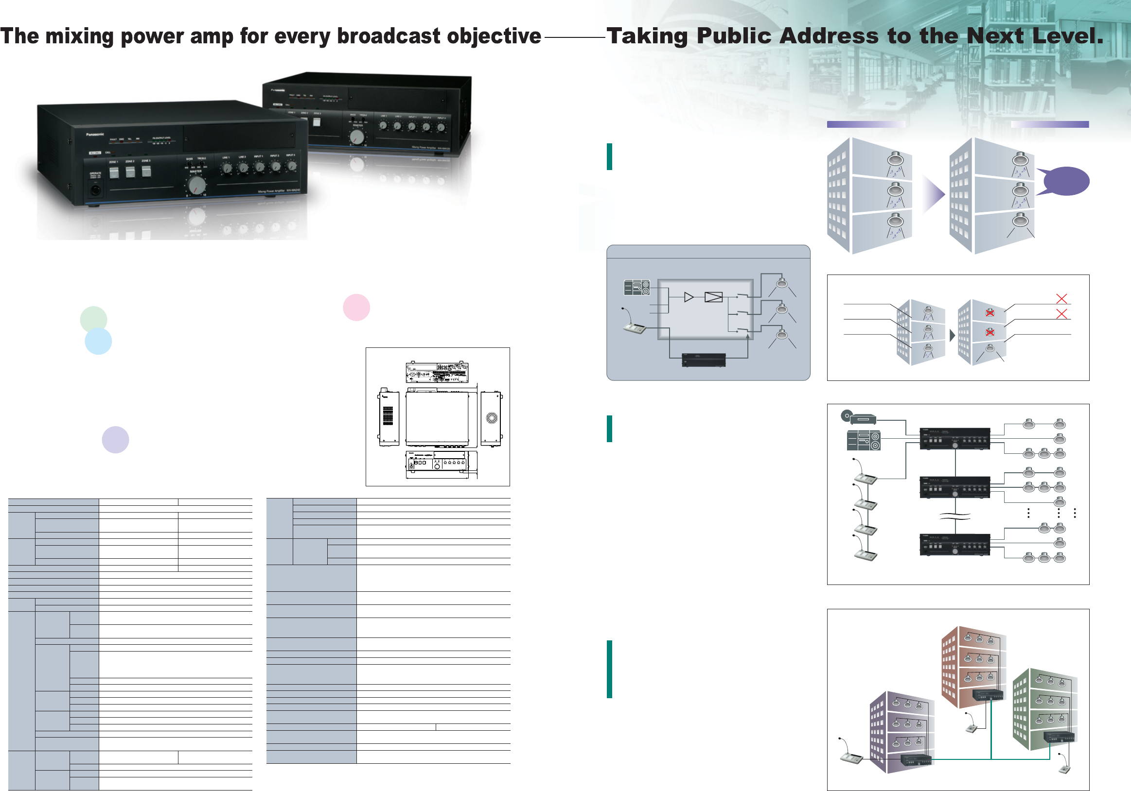
Addition of Booster Power Amplifier enables 2-channel
broadcast with separate transmissions delivered to different zones.
For example, a business-related message is transmitted
only to Zone 1 while background music continues to be
played throughout the building. Background music
continues in Zone 2 and Zone 3.
2-channel Broadcast
Add Up To 30 Zones
Depending on scale of application systems
may include up to ten (10) WA-MA120N or
WA-MA240N mixing power amplifiers for
expansion to up to 30 zones.
Background music and announcement
transmission can be transmitted independently
to any of three zones, with background music
transmitted to one zone and announcements
transmitted to another zone.
*2-channel broadcast requires the optional WA-BA240N
Booster Power Amplifier
Up To Four Remote
Microphones
Up to four (4) WR-210AE remote
microphones can be used to broadcast from
remote locations. These remote
microphones can be used for individual,
group, all-at-once or simultaneous
broadcast.
Broadcast
Simul
taneous
ly To
Multiple Remote Areas
For example, facilities with multiple buildings
can have a WA-MA120N or WA-MA240N
installed in each building. Via the simultaneous
broadcast BUS I/O connector, broadcasts can
be directed to selected all buildings at once.
2-channel Broadcast
Program Broadcast
With the optional WU-ZM001E Sound
Message Unit, an SD memory card can be
used to store MP3 data to be broadcast for
a week at specified days and times. The SD
memory card holds 100 messages.
Troubleshooting
The optional WU-ZS001E Surveillance
Unit checks at preset intervals (or 24-
hours a day) for overheating and sound
and speaker irregularities.
Message for ZONE 1 only, and BGM continues for ZONE 2 and 3.
Message for ZONE 1 only, BGM is stopped at ZONE 2 and 3.
2-channel
Broadcast
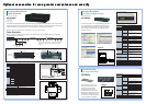
Loop through connections using the simultaneous broadcast BUS
I/0 connector allows you to transmit through multiple independent
units to all areas simultaneously.
In the illustration to the right, buildings A, B and C are each
equipped with its own Mixing Power Amplifier. Even so, an
emergency message can be transmitted simultaneously to
all three buildings.
Broadcast
Simultaneously
To Multiple
Remote Areas
Up to 10 units can be connected to increase capacity to 30 zones.
WA-MA120N / 240N
2-channel Broadcast Circuit Diagram
WA-BA240N
WR-210AE
BGM
Amplifier
Mixer
1-channel Broadcast
BUS Line
building A
NO.1(Master)
(Master)
WR-210AE
(up to 4 units)
WR-210AE
NO.2
NO.10
1
2
3
4
5
6
28
29
30
(BGM)
(BGM)
Attention ...
ZONE 3
(BGM)
ZONE 2
(BGM)
ZONE 1
(BGM)
ZONE 3
(BGM)
ZONE 2
(BGM)
ZONE 1
(Message)
Background
music
continue
ZONE 1 (BGM)
ZONE 2 (BGM)
ZONE 3 (BGM)
ZONE 1 (Message)
ZONE 2 (BGM)
ZONE 3 (BGM)
building B
building C
WR-201E
Each WA-MA120N (or WA-MA240N) can drive three
output channels. As indicated in the diagram on the right,
a system in which a single source drives up to 30 Zones
can be constructed.
Add Up To 30 Zones
Model No. WA-MA120N WA-MA240N
Power Source
AC : 110 V - 120 V or 220 V - 240 V (selectable), 50/60 Hz DC : +24 V, M3 screw terminal*
2
Power Non-operation mode (standby) 11 W 14 W
Consumption Under normal operating conditions 95 W 175 W
(AC) according to IEC60065
With rated output signal 330 W 680 W
Current Non-operation mode (standby) 0.1 A 0.1 A
Consumption Under normal operating conditions 4 A 8 A
(DC) according to IEC60065
With rated output signal 10 A 20 A
Rated Output 120 W 240 W
Frequency Response 50 Hz - 15 kHz, -3 ±3 dB
Distortion Less than 1 % at 1 kHz rated output
Signal- to-Noise Ratio More than 60 dB
Tone Control Bass : ±10 dB at 100 Hz, Treble : ±10 dB at 10 kHz
Volume EMG 0 dB to -20 dB
Control Others 0 dB to ∞ (off)
Audio Input INPUT 1-3 Audio MIC : -65 dBV / LINE : -22 dBV (selectable)
5 kΩ electronically balanced*
1
, XLR-3-11 type connector (female)
Control No-voltage make contact input, open voltage : +5 V DC,
(Only INPUT 1) short-circuit current : under 1 mA, Push-in terminal*
4
LINE 1,2 -22 dBV, 10 kΩ unbalanced, RCA pin jack x 2 (monaural)
RM Audio RM : -22 dBV / MIC : -65 dBV (selectable) 10 kΩ electronically balanced*
1
(Remote Control
No-voltage make contact input, open voltage : +5 V DC, short-circuit current : under 1 mA
Microphone
(1) CALL (2-channel announcement select) (2) BC (activation control of announcement)
Input) (3) ALL CALL (activation control of all-zone announcement)
(4) Z1 (zone 1 select) (5) Z2 (zone 2 select) (6) Z3 (zone 3 select)
Power Supply DC +24 V, 180 mA max. (Up to 4 Remote Microphones [WR-210E] can be connected)
Connector Push-in terminal*
4
TEL PAGING Audio -22 dBV, 10 kΩ electronically balanced*
1
(Telephone Paging Control
No-voltage make contact input, open voltage : +5 V DC, short-circuit current : under 1 mA
Input) Connector Push-in terminal*
4
EMG Audio 0 dBV, 10 kΩ electronically balanced
(Emergency Control
No-voltage make contact input, open voltage : +5 V DC, short-circuit current : under 1 mA
Equipment Input) Connector Push-in terminal*
4
INS IN (Insertion Input) 0 dBV, 100 kΩ unbalanced, RCA pin jack
ZONE 1 CALL IN 100 V or 70 V balanced, M3 screw terminal*
3
(for 2-channel Announcement)
Audio Output ZONE 1-3, Output Voltage 100 V / 83 Ω (changeable to 70 V / 42 Ω)
100 V / 42 Ω (changeable to 70 V / 21 Ω)
DIRECT OUT / Impedance
Connector M3 screw terminal*
3
SP4 Ω Impedance 4 Ω
(Low Impedance Connector M3 screw terminal*
3
Loudspeaker)
WR-201E
Mixing Power Amplifiers
WA-MA120N [120W]
WA-MA240N [240W]
Attention ...
Attention ...
DIMENSIONS
WA-MA120N / WA-MA240N
Unit: mm
29
14 375
420
132
SPECIFICATIONS
ZONES