4
Installation options
Attaching to a wall
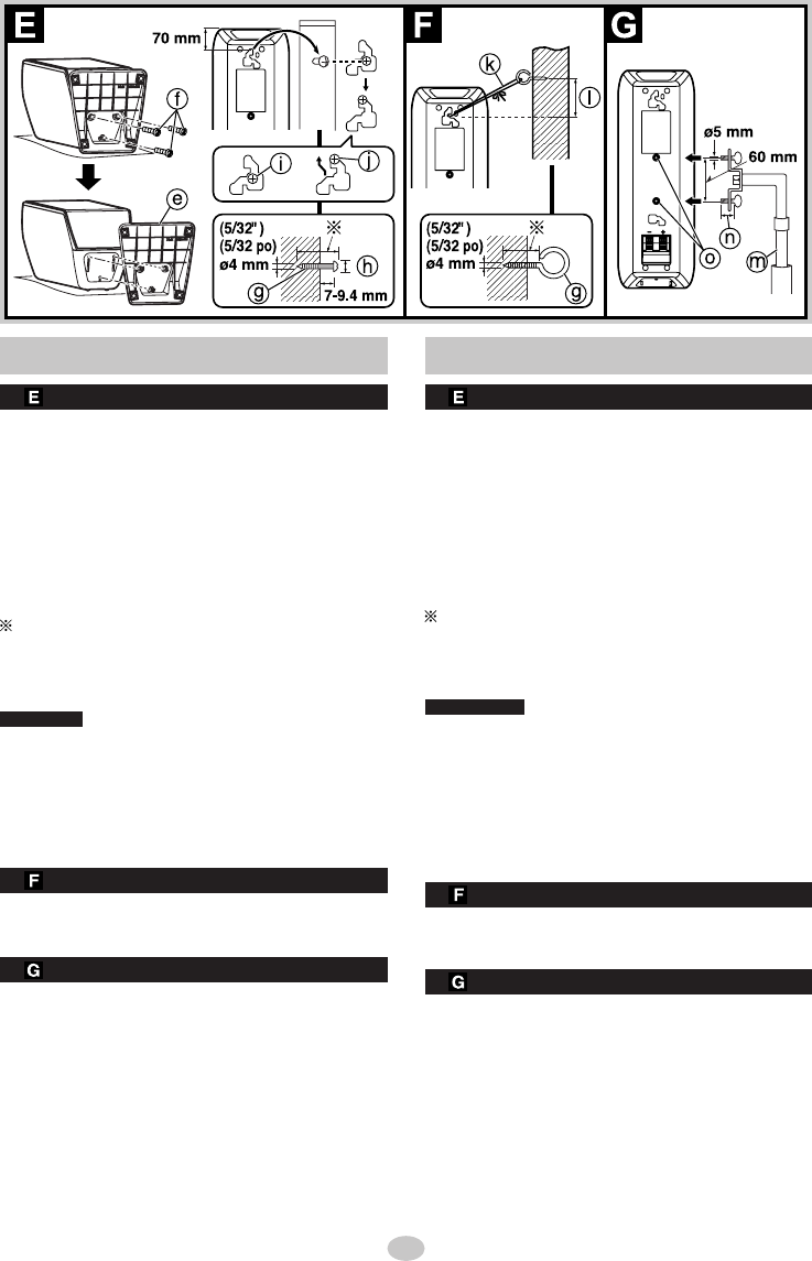
Detach the stand e.
f Remove the 3 screws.
Drive a screw g (not included) into the wall.
• Ensure that the screw g is positioned at least 70
mm (2-3/4″) away from the ceiling.
• h Ø7 to 9.4 mm (9/32″ to 3/8″)
The wall on which the speaker is to be mounted and
the screw g (not included) used for installing the
speaker must be strong enough to support a weight
of at least 10 kg (22 lb.). Consult the contractor in
charge of the work.
A screw which is at least 30 mm (1-3/16″) long (p
see above) is used when installing the speaker on
a wooden post or pillar. In all other cases, use a
screw which is strong enough to support a weight
of at least 10 kg (22 lb.).
CAUTION
Do not attach this speaker to walls or ceilings using
methods other than those described here.
Fit the speaker securely onto the screw with the hole.
i In this position, the speaker will likely fall if moved
to the left or right.
j Move the speaker so that the screw is in this
position.
Attaching a stabilizing wire
k Wire (not included) l
Approx. 150 mm (5-29/32″)
Drive a screw g (not included) into the wall. (p
see above (Attaching to a wall))
Attaching to speaker stands
Detach the stand. (p see above (Attaching to a wall))
m Speaker stands (not included)
n Plate thickness + 7 to 10 mm (9/32″ to 13/32″)
o Attach the stands with these holes.
Ensure the following conditions are met when you
purchase your speaker stands.
•
Observe the diameter and length of the screws and the
distance between screws as shown in the diagram.
Screw; diameter: 5 mm (3/16″), pitch: 0.8 mm (1/32″),
length: thickness of stand plate plus between 7 and
10 mm. Distance between the centers of the holes:
60 mm (2-3/8″)
•
The stands must be able to support over 10 kg (22 lb.).
• The stands must be stable even if the speakers are
in a high position.
Installations possibles
Fixation à un mur
Dégager le socle e.
f Retirer les trois vis.
Insérer une vis
g
(vendue séparément) dans le mur.
• S’assurer que la vis g est placée à une distance
d’au moins 70 mm (2 3/4 po) du plafond.
• h Ø7 à 9,4 mm (9/32 po
à
3/8 po)
Le mur sur lequel l’enceinte sera montée et la vis g
(non fournie) utilisée pour installer l’enceinte doivent
être assez solides pour supporter un poids d’au moins
10 kg (22 lb). Informez-vous auprès du contractant
responsable des travaux.
Une vis longue d’au moins 30 mm (1 3/16 po) (p
voir ci-dessus) est utilisée pour installer l’enceinte
sur un montant ou pilier de bois. Dans tous les
autres cas, utiliser une vis assez solide pour
supporter un poids d’au moins 10 kg (22 lb).
ATTENTION
Ne pas fi xer cette enceinte à un mur ou la suspendre
par des méthodes autres que celles décrites dans le
présent manuel.
Fixer l’enceinte au mur de façon sécuritaire en
insérant la vis dans le trou sur son panneau arrière.
i
Dans cette position, l’enceinte est susceptible de
tomber si elle déplacée vers la gauche ou la droite.
j Déplacer l’enceinte de manière que la vis soit dans
cette position.
Installation d’un fi l de stabilisation
k Fil (non fourni) l Environ 150 mm (5 29/32 po)
Insérer une vis
g
(vendue séparément) dans le mur.
(p
voir ci-dessus
(
Fixation à un mur
))
Fixation des enceintes sur un support
Dégager le socle. (p voir ci-dessus (Fixation à un mur))
m Supports (vendus séparément)
n
Épaisseur du support : 7 à 10 mm (9/32 po à 13/32 po)
o
Fixer le support aux orifi ces à l’arrière de l’enceinte.
Vérifi er les points suivants avant d’acheter des
supports pour enceintes:
•
Le diamètre, la longueur des vis ainsi que la distance
entre les vis doivent être comme illustré au schéma.
Les vis doivent avoir un diamètre de 5 mm (3/16 po) et un
pas de 0,8 mm (1/32 po). La longueur doit comprendre
l’épaisseur du support plus 7 à 10 mm. La distance entre
chaque orifi ce doit être de 60 mm (2 3/8 po).
•
Les supports doivent pouvoir supporter plus de 10 kg (22 lb).
• Les supports doivent être stables même lorsque les
enceintes sont placées en hauteur.


