


lCD audio:
98 dB
(4) Total harmonic distortion:
lCD audio:
0.0025 %
Digital audio output:
Coaxial digital output: Pin jack
Pickup
Wave length: 662 nm/785 nm
Laser power: CLASS 2/CLASS 3A
Note:
Specifications are subject to change without notice.
Mass and dimensions are approximate.
Solder:
This model uses lead free solder (PbF).
1 SAFETY PRECAUTIONS
4
1.1. GENERAL GUIDELINES
4
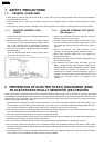
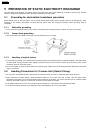
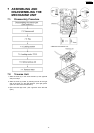
2 PREVENTION OF ELECTRO STATIC DISCHARGE (ESD) TO
ELECTROSTATICALLY SENSITIVE (ES) DEVICES
4
3 Precaution of Laser Diode
5
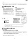
4 About lead free solder (PbF)
5
5 PREVENTION OF STATIC ELECTRICITY DISCHARGE
6
5.1. Grounding for electrostatic breakdown prevention
6
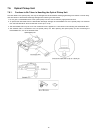
5.2. Handling Precautions for Traverse Unit (Optical Pickup)
6
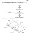
6 DISASSEMBLING THE CASING AND CHECKING P.C.B.S
7
6.1. Disassembly Procedure
7
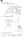
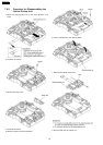
6.2. Casing Parts and P.C.B. Positions
7
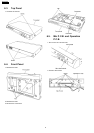
6.3. Top Panel
8
6.4. Front Panel
8
6.5. Mic P.C.B. and Operation P.C.B.
8
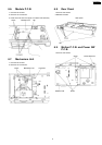
6.6. Module P.C.B.
9
6.7. Mechanism Unit
9
6.8. Rear Panel
9
6.9. Mother P.C.B. and Power SW P.C.B.
9
6.10. Service Position
10
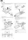
7 ASSEMBLING AND DISASSEMBLING THE MECHANISM UNIT
11
7.1. Disassembly Procedure
11
7.2. Traverse Unit
11
7.3. Tray
12
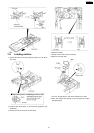
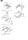
7.4. Loading section
13
7.5. Loading motor P.C.B.
14
7.6. Optical Pickup Unit 15
7.7. Traverse Motor
17
8 Self-Diagnosis Function and Service Modes
19
8.1. Optical Pickup Breakdown Diagnosis
19
8.2. Service Mode Table 1
20
8.3. DVD Self Diagnostic Function-Error Code
20
8.4. Last Error Code saved during NO PLAY
21
8.5. Service mode table 2
22
8.6. Sales demonstration lock function
24
8.7. Handling After Completing Repairs
24
9 Service Precautions
25
9.1. Recovery after the dvd player is repaired
25
9.2. Firmware version-up of the DVD player
25
10 ADJUSTMENT PROCEDURES
26
10.1. Service Tools and Equipment
26
10.2. Important points in adjustment
26
10.3. Storing and Handling Test Discs
26
10.4. Optical adjustment
27
11 Abbreviations
29
12 VOLTAGE CHART
31
12.1. MOTHER P.C.B.
31
12.2. MODULE P.C.B.
32
12.3. MIC P.C.B.
33
13 BLOCK DIAGRAM
35
13.1. OVERALL BLOCK DIAGRAM
35
13.2. POWER SUPPLY BLOCK DIAGRAM
36
13.3. SERVO BLOCK DIAGRAM
37
CONTENTS
Page Page
2
DVD-K29GCS