7
Model 7900 7-Channel Power Amplifier
Owner’s Manual
Connecting Your Amplifier
When using banana plugs, connections may be made by simply inserting the
jack affixed to your speaker wire into the hole provided on the rear of the colored
screw caps on the binding posts. Before using banana type jacks make certain
that the plastic screw caps are firmly tightened down by turning them in a
clockwise direction until they are snug against the chassis. This will insure that
the maximum surface area of the plug is in contact with the jack. Be certain
to observe proper polarity.
Run the cables to the speaker locations. It is recommended that the length of wire
connecting any pair of speakers be similar. For example, make certain that the
wire length connecting the left and right front, or the left and right rear (surround)
speakers are similar in length, even though one speaker may be physically closer
to the amplifier than the other. Do not coil any excess cable, as this may become
an inductor that creates frequency response variations in your system.
Finally, connect the wires to the speakers, again being certain to observe proper
polarity. Remember to connect your negative, or black wire, to the matching
terminal on the speaker. The positive, or red wire should be connected to the
matching terminal on the speaker.
NOTE: While most speaker manufacturers adhere to an industry conven-
tion of using red terminals for positive connections and black terminals
for negative, some manufacturers may vary from this configuration. To
assure proper phase connections, and optimal performance, consult the
identification plate on your speaker terminals, or the speaker’s manual
to verify polarity. If you do not know the polarity of your speaker, consult
the speaker’s manufacturer for further information.
Ground Wire Connection
Your Outlaw amplifier features a ground terminal to help reduce the likeli-
hood of ground loop potential issues between components in your system.
First, connect a thin gauge wire (20-24 gauge speaker wire is sufficient) to
the Model 7900’s ground terminal. Connect the other end of your ground
wire to the back of your pre-amp processor’s ground terminal (not the one
supplied for your phono stage). In the event that your processor does not have
a dedicated ground terminal, you will need to use one of the chassis screws
on its rear panel.
In these instances, it may be necessary to scratch some of the paint away behind
the chassis screw in order to provide a path to ground.
Power Control Connections
Your Outlaw amplifier features a built-in remote turn-on system that will
automatically switch the amplifier on when another device in the system is
switched up.
Remote Turn-On Using Products Equipped With a
12 Volt Trigger Jack
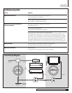
Press the front panel power switch on the amplifier so that it is in the ON posi-
tion. Then, using an accessory cable with a 3.5mm mono mini-plug on each
end, connect the trigger-output jack on the rear of the source device to the
trigger input jack on the back panel of the amplifier. When these connections
are made, the amplifier will automatically turn on whenever the triggering
device is turned on.
Remote Turn on Using External AC to DC Power Converter
If your processor or receiver does not have a dedicated trigger jack, it is still
possible to activate the unit for automatic turn on when a Switched Outlet
is available on the rear of the source device. To control the amplifier in this
fashion you will need a small AC to DC power converter, capable of delivering
a 3 to 24 volt 5mA DC signal. The DC voltage should terminate in a standard
3.5mm type mini plug. This type of converter may be obtained as a Power
Adapter from many electronics retailers.
When installing, press the Main Power Switch on the front panel of the amplifier
in so that it is in the ON position. Plug the AC adapter into a switched outlet that
will be activated when you wish to have the amplifier turn on. This may be the
switched outlet at the rear of an AV receiver or other audio equipment. Connect
the 3.5mm mini-plug from the adapter to the trigger-input jack on the back
panel of the amplifier. The amplifier will now turn on and off automatically,
based on the status of the controlling device.
Power Connection
Once all audio and system connections have been made, connect the supplied
power cords to the amplifier first, and then connect them to separate AC outlets.
Please make certain that the amplifier is turned off and that the device con-
nected to the remote trigger input is off when connecting the power cord and
plugging it into an AC outlet. Do not use extension cords, outlet power strips,
surge protectors or power conditioners unless they are capable of handling the
current draw of the Model 7900.
NOTE: In order to meet full rated output, the Model 7900's power cables
must be connected to two different branches of your electrical system (Ie.
two separate circuits). Failure to do so will limit the Model 7900's overall
power output capability and can lead to tripped circuit breakers.
CAUTION: Do not plug the Model 7900 into the Switched Accessory outlet
of another device! These outlets are intended for use with low current draw
products, such as tuners, CD players or cassette decks. These switched
outlets cannot handle the high current draw of a power amplifier. Using
these outlets for a power amplifier is a significant safety hazard.
IMPORTANT NOTE: The Model 7900 eliminates turn-on power surges
by employing an improved power controller which delays full start-up
about 25 seconds, allowing the unit to stabilize properly. Do not attempt
to play audio until the unit is ready and the power indicator light turns blue.
If multiple amplifiers are connected on the same circuit, there will be
insufficient power available for full-power operation. This may create a
fire hazard and cause mains breakers to trip. If you are using multiple
amplifiers, make sure they are connected to their own circuit.


