


48
Connecting Your Components
—Continued
■
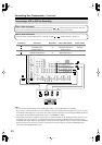
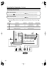
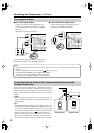
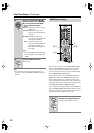
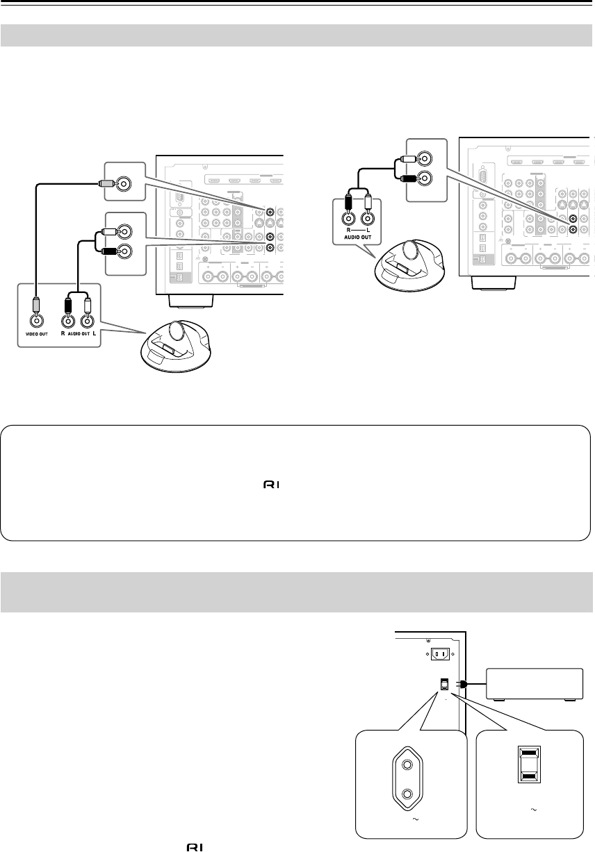
If Your iPod Supports Video:
Connect your RI Dock’s audio output jacks to the
AV receiver’s GAME/TV IN L/R jacks, and connect
its video output jack to the AV receiver’s GAME/TV
IN V jack.
(Onkyo DS-A2 hookup shown below.)
If you have an Onkyo DS-A1 RI Dock, connect its video
output jack to the AV receiver’s GAME/TV IN S jack.
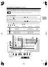
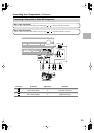
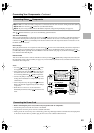
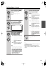
■
If Your iPod Doesn’t Support Video:
Connect your RI Dock’s audio output jacks to the
AV receiver’s GAME/TV IN L/R jacks.
(Onkyo DS-A2 hookup shown below.)
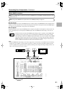
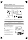
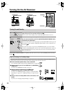
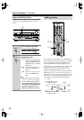
The AV receiver has AC outlets on its rear panel that can be used to
connect the power cords of other components that you intend to use
with the AV receiver. These components can then be left turned on so
that they turn on and off as and when the AV receiver is set to On or
Standby.
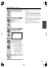
Caution:
• Make sure that the total capacity of the components that you con-
nect to the AC OUTLETS does not exceed the stated capacity (e.g.,
TOTAL 120 W).
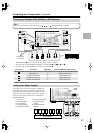
Notes:
• When the HDMI Control setting is set to Enable (page 109), the
AC outlets are on all the time regardless of whether the AV receiver
is set to On or Standby, or Ready mode in this case, so any compo-
nents connected to them cannot be turned on or off automatically.
• Onkyo components connected via should be connected
directly to a wall outlet, not an AC OUTLET on the AV receiver.
• The number of AC OUTLETS, socket type, and total capacity
depends on the country in which you purchased the AV receiver.
Connecting an RI Dock
RS232
DIGITAL
COAXIAL
OPTICAL
REMOTE
CONTROL
IN 1
IN 1
IN 2
IN IN IN IN
PHONO
FRONT R
FRONT R
(BTL)
SURR BACK R
CD TAPE AUX 1
GAME/TV
GAME/TV CBL/S
A
CBL/S
A
AUX 1
GND
IN 2
IN 3
LL
V
S
RR
ASSIGNABLE
(DVD)
(CBL/SAT)
(VCR/DVR)
(GAME/TV)
(CD)
OUT
COMPONENT VIDEO
ASSIGNABLE
IN 3
Y
C
B
/P
B
C
R
/P
R
IN 2 IN
1(DVD)
MONITOR
OUT
OUT
IN IN
Bi-AMP
HDMI
I
N
IN 2IN 3IN 4
ASSIGNABLE
ZONE2 R
ASSIGNABLE
L
R
IN
GAME/TV
V
GAME/TV
RS232
DIGITAL
COAXIAL
OPTICAL
REMOTE
CONTROL
IN 1
IN 1
IN 2
IN IN IN IN
PHONO
FRONT R
FRONT R
(BTL)
SURR BACK R
CD TAPE AUX 1
GAME/TV
GAME/TV CBL/SAT
CBL/SAT
AUX 1
GND
IN 2
IN 3
LL
V
S
RR
ASSIGNABLE
(DVD)
(CBL/SAT)
(VCR/DVR)
(GAME/TV)
(CD)
OUT
COMPONENT VIDEO
ASSIGNABLE
IN 3
Y
C
B
/P
B
C
R
/P
R
IN 2 IN
1(DVD)
MONITOR
OUT
OUT
IN IN
O
U
Bi-AMP
HDMI
IN 1IN 2IN 3IN 4
ASSIGNABLE
ZONE2 R
ASSIGNABLE
L
R
IN
GAME/TV
Connecting the Power Cords of Other Components (North American and
European models only)
Notes:
• Enter the appropriate remote control code before using the AV receiver’s remote controller for the first time (see
page 127).
• Connect the RI Dock to the AV receiver with an cable (see page 49).
• Set the RI Dock’s RI MODE switch to HDD or HDD/DOCK.
• Set the AV receiver’s Input Display to DOCK (see page 57).
• See the RI Dock’s instruction manual for more information.
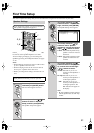
AC OUTLET
AC INLET
AC 120V
SWITCHED
120W 1A MAX.
60Hz
AC OUTLET
AC 120V
SWITCHED
120W 1A MAX.
60Hz
AC OUTLET
AC 220-240V
SWITCHED
100W 0.45-0.41A MAX.
50/60Hz
European model American model