5
Getting to know Your Speaker Package
A
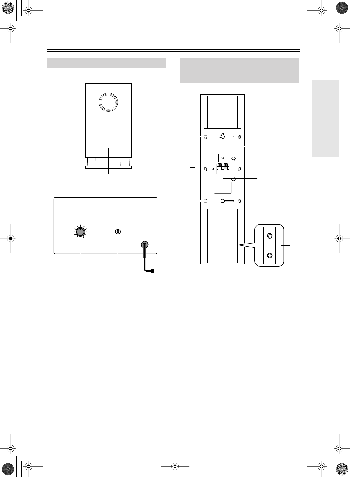
STANDBY/ON indicator
Red: Subwoofer in standby mode
Green: Subwoofer on
With the Auto Standby function, the SKW-240
automatically turns on when an input signal is
detected in Standby mode. When there’s no input
signal for about 20 minutes, the SKW-240 automat-
ically enters Standby mode.
B
OUTPUT LEVEL control
This control is used to adjust the volume of the sub-
woofer.
C
LINE INPUT
This RCA input should be connected to the sub-
woofer preout on your DR-S2.2 DVD Receiver,
amp, or other receiver with supplied RCA cable.
Note:
The Auto Standby function turns the subwoofer on when
the input signal exceeds a certain level. If the Auto
Standby function does not work reliably, try slightly
increasing or decreasing the subwoofer output level on
your receiver or amp.
1
Speaker terminals
These push terminals are for connecting the speaker
to your DR-S2.2 DVD Receiver, amp, or other
receiver with the supplied speaker cables. The sup-
plied speaker cables are color-coded for easy identi-
fication. Simply connect each cable to the same-
colored positive speaker terminal.
2
Keyhole slots
These keyhole slots can be used to wall-mount the
speaker either horizontally or vertically.
3
Speaker mount/bracket inserts
These threaded inserts can be used to attach the
speaker either horizontally or vertically to a speaker
mount or bracket.
Note:
Use commercially available 1/4-inch machine
screws to attach the speaker to a speaker mount or
bracket.
4
Base/stand inserts (other than center
speaker)
These threaded inserts can be used to mount the
speaker on the supplied base (screws included) or an
optional Onkyo speaker stand (AS-240).
Subwoofer (SKW-240)
1
OUTPUT
LEVEL
LINE
INPUT
MAX
MIN
23
■
Front
■ Rear
To AC outlet
Front, Center & Surround Speakers
(SKF-240F, SKC-240C, SKM-240S,
SKB-240)
2
4
1
3


