


C-701A
NOTE
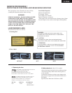
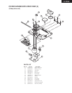
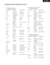
1. Removement of tray
1. Remove the top cover
2. Turn the locked screw to the clockwise to release the lock of gear.
(Refer to fig-1)
Lock
Unlock
Bottom side
Fig-1
3. Pull out the tray.
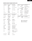
4. Remove the stopper. (Refer to fig-2)
5. Press the tray stopper to the arrow mark direction and remove
the tray ass'y. (Refer to fig-3)
Fig-2
Stopper
Tray
Fig-3
Tray
stopper
Tray
stopper
Front
Front
Front
SERVICE PROCEDURES 2
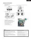
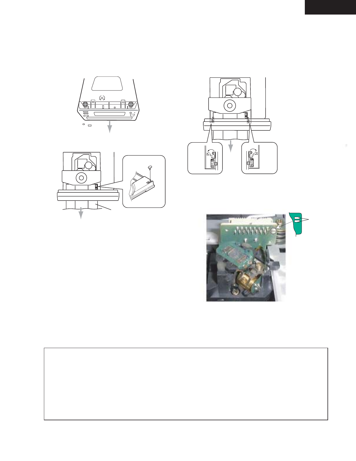
2. Replacement of optical pick-up
The laser diode in the optical pickup block is so sensitive to static
electricity, surge current and etc. that the components are liable to
be broken down or its reliability remarkably deteriorated.
During repair, carefully take the following precautions.
1. Solder the LD short terminal on mechanism.
2. Disconnect the flexible flat cable P101.
3. Replace the optical pickup.
4. Connect the flexible flat cable P101.
5. Unsolder the LD short terminal on mechanism.
Pick up short land
LD Short
Terminal
1. Ground for the work-desk.
Place a conductive sheet such as a sheet of copper
(with impedance lower than 10Mohm) on the work-
desk and place the set on the conductive sheet so that
the chassis can be grounded.
2. Grounding for the test equipments and tools.
Test equipments and toolings should be grounded in
order that their ground level is the same the ground of
the power source.
3. Grounding for the human body.
Be sure to put on a wrist-strap for grounding whose
other end is grounded.
Be particularly careful when the workers wear
synthetic fiber clothes, or air is dry.
4. Select a soldering iron that permits no leakage and
have the tip of the iron well-grounded.
5. Do not check the laser diode terminals with the
probe of a circuit tester or oscilloscope.