Features.
l Field Programmable Input and Output Ranges.
l 29 Predefined Math Functions.
l 12 Bit Resolution. (0.025%)
l Input to Output Isolation 1.6kV.
l High Accuracy 0.1%.
l Universal AC/DC Power Supply.
l Compact DIN Rail Mount Enclosure.
l 120 Point User Definable Curve Fitting.
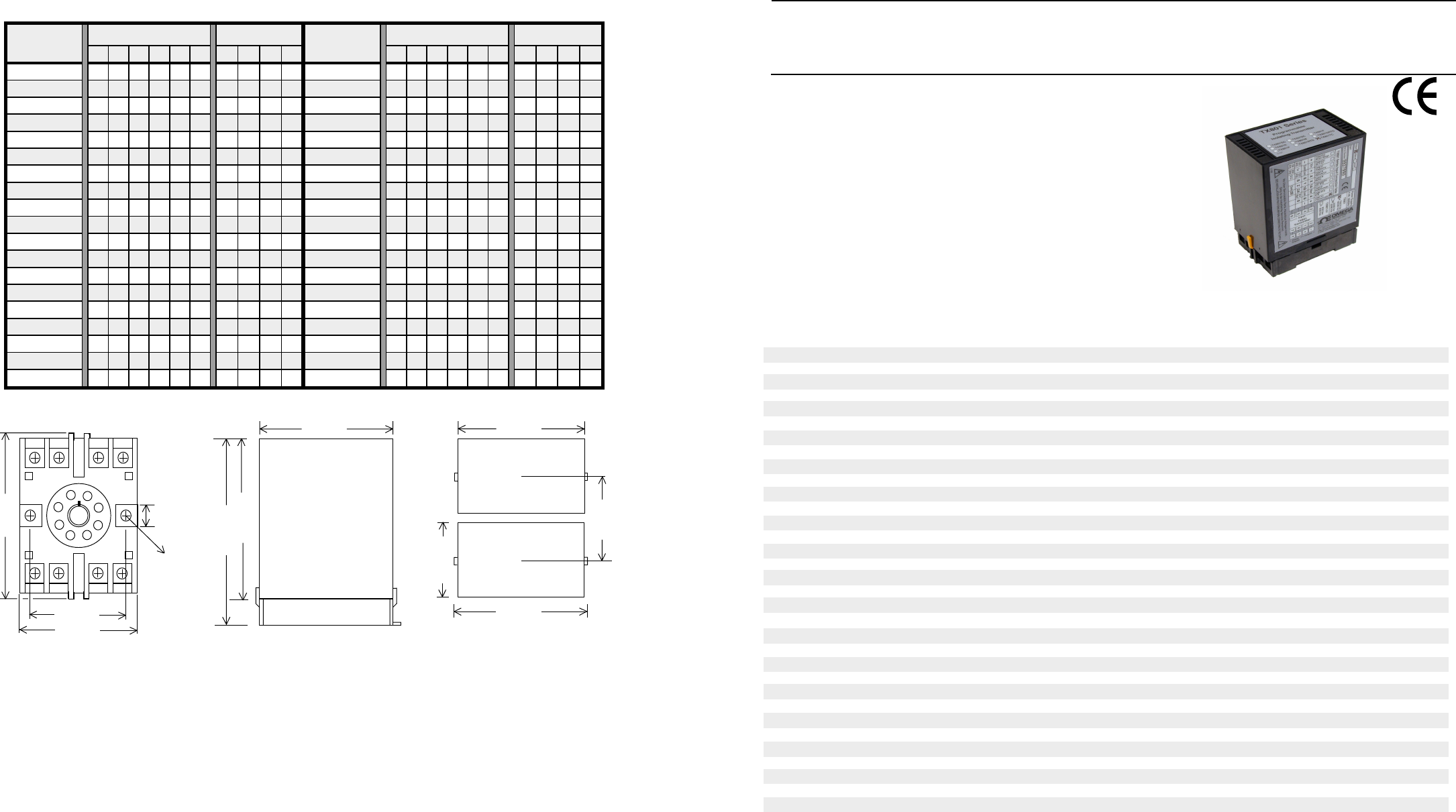
TX801M Programmable Isolating
Maths Function Transmitter.
Programmable Isolating Maths
Function Input to DC Current or
DC Voltage Output Transmitter.
TX801M Specifications.
Input -Voltage Field Programmable 0~5Vdc / 0~10Vdc / 1~5Vdc / 2~10Vdc.
Minimum Input Resistance = 180kΩ.
Maximum Over-range = 24Vdc Continuous.
-Current Field Programmable 0~20mAdc / 4~20mAdc.
Input Resistance = 250Ω.
Maximum Over-range = 50mAdc Continuous.
-Maths Functions 29 Field Selectable, Predefined, Maths Functions.
RS-232 Interface for Calibration and Testing. (Using a PI-RAC.)
-User Defined Curve Up to 120 Point Look-up Table, Linear Interpolation Between Points.
RS-232 Interface for Programming of User Curves. (Using a PI-RAC.)
IMPORTANT: The RS-232 communications port is NOT ISOLATED from the TX801M inputs.
Universal P/S -Standard High (H) 70~270Vac and 80~380Vdc; 50/60Hz; 4VA.
-Standard Mid (M) 24~80Vac and 20~90Vdc; 50/60Hz; 4VA.
-Low Voltage (L) 8~30Vac and 8~30Vdc; 50/60Hz; 4VA.
-Circuit Sensitivity <±0.001%/V FSO Typical.
Resolution -Input 12 Bit.
-Output 12 Bit.
Accurate to <±0.1% FSO Typical.
Linearity & Repeatability <±0.1% FSO Typical.
Ambient Drift <±0.01%/C FSO Typical.
Noise Immunity 125dB CMRR Average. (1.6kV Peak Limit.)
R.F. Immunity <1% Effect FSO Typical.
Isolation Voltage 1.6kVac/dc Peak Input to Output for 60sec.
Response Time 200msec Typical. (10 to 90% 100msec Typical.)
Note. The %RH Function has Software Dampening of 2sec Typical.
Operating Temperature 0~70C.
Storage Temperature -20~80C.
Operating Humidity 90%RH Max. Non-Condensing.
Construction Socket Plug-In Type With Barrier Terminals.
Relative Humidity -Input 0~100C for Input Range.
(Function 29) -Range 0~100%RH Over 0~100C Input.
-Accurate to <±1% FSO Typical.
Note 1. Refer to IN-HWD Humidity and Temperature Converter for Wet and Dry Bulb installation guide.
Note 2. Specifications based on Standard Calibration Unit, unless otherwise specified.
Note 3. Due to ongoing research and development, designs, specifications, and documentation are subject to change without notification.
No liability will be accepted for errors, omissions or amendments to this specification.
Quality Assurance Programme.
The modern technology and strict procedures of the ISO9001 Quality Assurance Programme applied
during design, development, production and final inspection grant long term reliability of the instrument.
The Proper Installation & Maintenance of TX801M.
MOUNTING.
(1) Mount in a clean environment in an electrical cabinet on 35mm, symetrical, mouning rail.
(2) Do not subject to vibration or excess temperature or humidity variations.
(3) Avoid mounting in cabinets with power control equipment.
(4) To maintain compliance with the EMC Directives the TX801M is to be mounted in a fully enclosed steel cabinet. The cabinet
must be properly earthed, with appropriate input / output entry points and cabling.
WIRING.
(1) A readily accessible disconnect device and overcurrent device must be incorporated in the the power supply wiring.
(2) All cables should be good quality overall screened INSTRUMENTATION CABLE with the screen earthed at one end only.
(3) Signal Cables should be laid a minimum distance of 300mm from any power cables.
(4) For 2 wire current loops and 2 wire voltage signals or 2 wire current signals, Austral Standard Cables B5102ES is
recommended. For 3 wire transmitters Austral Standard Cables B5103ES is recommended.
(5) It is recommended that you do not ground current loops and use power supplies with ungrounded outputs.
(6) Lightning arrestors should be used when there is a danger from this source.
(7) Refer to diagrams for connection information.
COMMISSIONING.
(1) Once all the above conditions have been carried out and the wiring checked apply power to the PI-M and allow five minutes
for it to stabilize.
(2) Take a low (approx 10%) and high (approx 90%) reading of the variable being measured by the transducer supplying
the signal to the PI-M, and ensure that this agrees with the level being indicated by the PLC or indicator, etc, that the TX801M
is connected into. Adjust for any difference using the Zero and Span trimpots in the top of the PI-M enclosure with a small
screwdriver until the two levels agree. (Clockwise to increase the output reading and anti-clockwise to decrease the output
reading.)
MAINTENANCE.
(1) Repeat (2) of Commissioning.
(2) Do it regularly - at least once every 12 months.
Dimensions and Mounting.
2 1 8 7
3 4 5 6
40mm
50mm
80mm
8.4mm
2 x 4.5mm
8PFA Octal Termination Base
80mm
Side View
120mm
Top View
51mm
84mm
80mm
100mm
Top View
58mm
Minimum distance
between units.
tuptuO
)V(egnaR
NAPS-1S noitcnuF-2S
tuptuO
)I(egnaR
NAPS-1S noitcnuF-2S
1 2 3 4 5 6 1 2 3 4 1 2 3 4 5 6 1 2 3 4
Vm005~0
011111 0011 Am1~0 011111 0000
V1~0 1 0 1 1 1 1 0 0 1 1 Am2~0 1 0 1 1 1 1 0 0 0 0
V2~0
110111 0011 Am5~0 010111 0000
V3~0 1 0 0 1 1 1 0 0 1 1 Am01~0 1 0 1 0 1 1 0 0 0 0
V4~0
111011 0011 Am61~0 111101 0000
V5~0 1 0 1 0 1 1 0 0 1 1 Am02~0 1 1 0 1 0 1 0 0 0 0
V6~0
110011 0011 Am5~1 110111 1000
V8~0 1 1 1 1 0 1 0 0 1 1 Am01~2 1 1 1 0 1 1 1 0 0 0
V01~0
110101 0011 Am02~4 111101 1000
V21~0 1 1 1 0 0 1 0 0 1 1 Am1~1- 1 0 1 1 1 1 0 1 0 0
V5~1
111011 10 11 Am2~2- 110111 0100
V01~2 1 1 1 1 0 1 1 0 1 1 Am5~5- 1 0 1 0 1 1 0 1 0 0
V1~1-
110111 0111 Am01~01- 110101 0100
V2~2- 1 1 1 0 1 1 0 1 1 1 Am02~02- 1 1 1 0 1 0 0 1 0 0
V5~5-
110101 0111 *Am01-~0 10 10 11 0000
V01~01- 1 1 1 0 1 0 0 1 1 1 *Am02-~0 1 1 0 1 0 1 0 0 0 0
V21~21-
111100 0111
*V5-~0 1 0 1 0 1 1 0 0 1 1
*V01-~0 110101 0011
Output Range Programming Table.
Notes: 1/ Switch status 1 = ON 0 = OFF
2/ Output ranges with '*' beside them reverse the polarity of the output connections.


