


TX801D RTD Programmable
Programmable Isolating
Differential RTD Transmiter
Programmable, Isolating, 3 Wire
RTD Input to DC Current or DC
Voltage Output Transmitter.
Quality Assurance Programme.
The modern technology and strict procedures of the ISO9001 Quality Assurance Programme applied
during design, development, production and final inspection grant long term reliability of the instrument.
Features.
l Field Programmable Input and Output Ranges.
l Bi-Polar Input and Output Ranges.
l Isolated Input to Output 1.6kV.
l High Accuracy & Linearity to 0.1%.
l Linear With Temperature.
l Universal AC/DC Power Supply.
l Compact DIN Rail Mount Enclosure.
l Available Standard or Special Calibration.
ISO9001
E
G
I
S
T
E
R
R
E
D
S
U
P
P
I
R
E
L
Specifications.
RTD Input Pt100 DIN (2 Wire Type) Standard.
Sensor Current = 0.8mA Typical.
Field Programmable Zero From -200C(-400F) to 200C(400F).
Field Programmable Span From 20C(40F) to 600C(1200F).
Other Types of RTD Available:
JIS Pt100, Pt250, Pt500, Pt1000, CU10, CU100, Ni100 or Specified.
Output - Voltage Field Programmable From 500mVdc to ±12Vdc.
Maximum Output Drive = 10mA.
- Current Field Programmable From 1mAdc to ±20mAdc.
Maximum Output Drive = 10Vdc. (500Ω @ 20mA.)
Universal P/S -Standard High (H) 70~270Vac and 80~380Vdc; 50/60Hz; 4VA.
-Standard Mid (M) 24~80Vac and 20~90Vdc; 50/60Hz; 4VA.
-Low Voltage (L) 8~30Vac and 8~30Vdc; 50/60Hz; 4VA.
-Circuit Sensitivity <±0.001%/V FSO Typical.
Accurate to <±0.1% FSO Typical.
Linearity & Repeatability <±0.1% FSO Typical.
Ambient Drift <±0.01%/C FSO Typical.
Noise Immunity 125dB CMRR Average. (1.6kV Peak Limit.)
R.F. Immunity <1% Effect FSO Typical.
Isolation Voltage 1.6kVac/dc Input to Output for 60 sec.
Response Time 200msec Typical. (10 to 90% 50msec Typical.)
Operating Temperature 0~70C.
Storage Temperature -20~80C.
Operating Humidity 90% RH Max. Non-Condensing.
Construction Socket Plug-In Type with Barrier Terminals.
Note 1. Specifications based on Standard Calibration Unit, with RTD 2 at 0C, unless otherwise specified.
Note 2. Due to ongoing research and development designs, specifications, and documentation are subject to change without notification.
No liability will be accepted for errors, omissions or amendments to this specification.
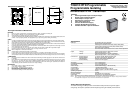
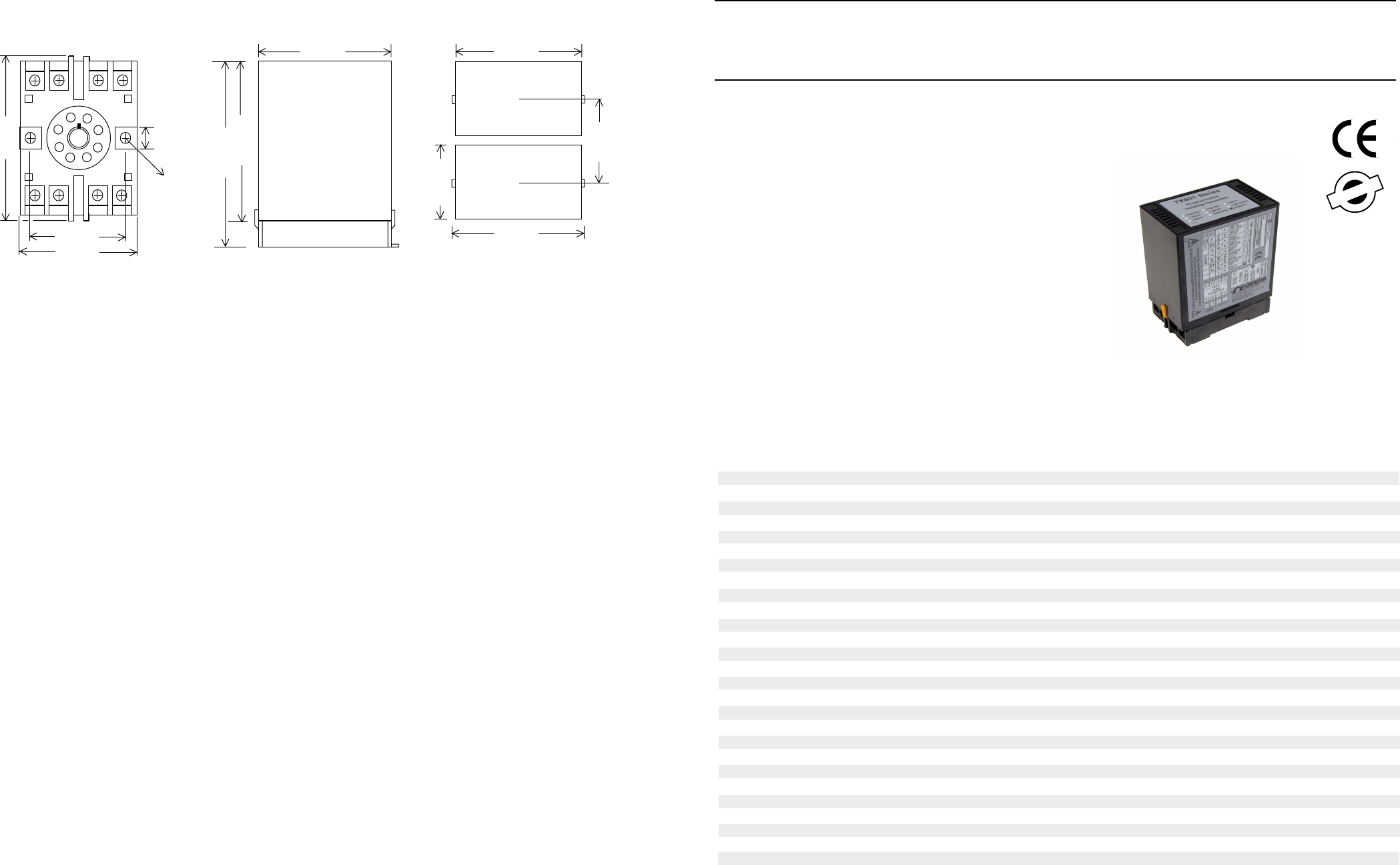
2 1 8 7
3 4 5 6
40mm
50mm
80mm
8.4mm
2 x 04.5mm
8PFA Octal Termination Base
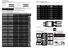
Dimensions and Mounting.
80mm
Side View
120mm
Top View
51mm
84mm
80mm
100mm
Top View
58mm
Minimum distance
between units.
The Proper Installation & Maintenance
MOUNTING.
(1) Mount in a clean environment in an electrical cabinet on 35mm, symetrical, mounting rail.
(2) Do not subject to vibration or excess temperature or humidity variations.
(3) Avoid mounting in cabinets with power control equipment.
(4) To maintain compliance with the EMC Directives the TX801D RTD is to be mounted in a fully enclosed steel cabinet. The
cabinet must be properly earthed, with appropriate input / output entry points, filtering and cabling.
WIRING.
(1) A readily accessible disconnect device and overcurrent device must be incorporated in the the power supply wiring.
(2) All cables should be good quality overall screened INSTRUMENTATION CABLE with the screen earthed at one end only.
(3) Signal cables should be laid a minimum distance of 300mm from any power cables.
(4) For 2 wire current loops and 2 wire RTDs, Austral Standard Cables B5102ES is recommended. For three wire transmitters
and 3 wire RTDs Austral Standard Cables B5103ES is recommended.
(5) For differential 2-wire RTD measurement it is important to use identical cables and keep them the same length, so errors
due to cable length are kept minimal.
(6) It is recommended that you do not ground current loops and use power supplies with ungrounded outputs.
(7) Lightning arrestors should be used when there is a danger from this source.
(8) Refer to diagrams for connection information.
RTD'S.
(1) Avoid locating the RTD where it will be in a direct flame.
(2) Locate it where the average temperature will be measured. It should be representative of the mass.
(3) Immerse the RTD so that the measuring point is entirely in the temperature to be measured; 9 to 10 times the diameter
of the protection tube is recommended. Heat that is conducted away from the measuring point causes an error in reading.
COMMISSIONING.
(1) Once all the above conditions have been carried out and the wiring checked apply power and allow five minutes for it
to stabilize.
(2) Due to differences in cable resistance in the RTD legs or errors within the RTD itself a small Zero error may occur (usually
less than 1C). To remove this error use two calibration standard RTDs at the same immersion depths and adjust the
Zero trimpot in the top of the enclosure with a small screwdriver, until the two levels agree. (Clockwise to increase the
output reading and anti-clockwise to decrease the output reading.)
MAINTENANCE.
(1) Check RTDs in place - with the calibration RTDs
at the same immersion depths.
(2) Do it regularly - at least once every 6 months.
(3) Replace defective protection tubes - even if they
look good they may not be fluid or gas tight.
(4) Check cables entering the RTD sensor heads.