


START HERE
2
34
DRN-PR
PROCESS INPUT
General Description:
The DRN Series of DIN rail-mountable signal conditioners are
available for Thermocouple, RTD, Strain, Process, AC Voltage,
AC Current and Pulse/Totalizer input types.
The factory calibrated signal conditioners are ideal for all
process and power monitoring applications, they feature 3-
way isolation, high accuracy input, programmable outputs,
and are excellent front end interfaces for programmable logic
controllers or data acquisition systems. For maximum user
configurability the signal conditioners allow complete input-
output scaling via a RS-232 connection to any PC or PLC.
Software Description:
The signal conditioner configuration program is a MS
DOS/Windows program (this manual is for the Windows
version). It is designed especially for the DRN Series Signal
Conditioner. This program will run on any PC with Windows
application and will start automatically.
Free Serial Communication software and ActiveX Controls
are on the CD-ROM enclosed with this shipment.
To download the latest software release
(or request a free CD-ROM) please go to:
www.omega.com/software
What You need:
¥Your choice of the signal conditioner
¥IBM PC or compatible
¥Windows software 3.1 or higher, or Windows 95/98
¥RJ12 connector with telephone cable
¥Adapter (DB9 or DB25 to RJ12)
Setting up your System
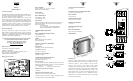
+
-
N/C
SIGNAL INPUT
J3
++
+
ANALOG OUTPUT LINEARITY:
0.1% of FS
ANALOG OUTPUT STEP RESPONSE TIME:
2 seconds to 99% of final value
INPUT POWER:
10 to 32 Volt DC
POWER CONSUMPTION:
3 watts (125 mA at 24Vdc)
OPERATING AMBIENT:
-5 to +55 ¡C
STORAGE TEMPERATURE:
-40 to +85 ¡C
RELATIVE HUMIDITY:
90% at 40 ¡C non-condensing
DIMENSIONS:
Introduction:
The Process input signal conditioners are high performance
instruments that measure DC currents/voltages in 6 ranges
which are as follows:
±20mA; ±400mV, ±1Volt, ±2Volts,
±5Volts, and ±10V
olts. Key features of the signal
conditioners are operation in linear or square root and process
totalize modes, scalable analog output and a simple RS232
interface for scaling analog output and range selection. The
RS232 interface may also be used for digital transmission of
input signal to a computer or a PLC. Additional features
include three way isolation between DC power, signal input
and analog output/RS232.
INPUT RANGES:
±20mA; ±400mV, ±1V, ±2V, ±5V, and ±10V
Ratiometric or nonratiometric
EXCITATION:
14V or 10V @ 25mA
INPUT IMPEDANCE:
Voltage Range: 1M½
Current Range: 10½
ISOLATION:
Dielectric strength to 1000 Vrms transient per 1 minute test
based on EN 61010 for 50 Vdc or Vrms working voltage.
Three way Isolation:
¥ Power to input
¥ Power to analog output/communication
¥ Input to analog output/communication
COMMON MODE REJECTION:
100dB
INPUT OVER-RANGE PROTECTION:
Voltage input: 50V
Current input: 50mA
MODE:
Linear, Square root, Linear totalize,
Square root totalize
ANALOG TO DIGITAL TECHNIQUE:
Multiple slopes
READ RATE:
8 readings/second, automatic polarity
ACCURACY AT 25 ¡C:
±0.1% of FS ± 2 counts
TEMPERATURE STABILITY:
100 ppm/¡C typical
STEP RESPONSE FOR RS232 OUTPUT:
2 seconds to 99% of the final value
(Filter time constant = 64)
RESPONSE TIME:
To verify the response time, check the carriage return <CR>, it
will be sent at the end of the response. You can send another
command after you receive the <CR>.
i.e. send: *X01 response: X01<DATA><CR>
WARM UP TO RATED ACCURACY:
30 minutes
ANALOG OUTPUT SIGNAL TYPE:
Voltage: 0-10 Volt, maximum current 10mA
Current: 0-20 mA or 4-20 mA, maximum compliance voltage
10 Volts (maximum loop resistance 500½)