


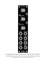

Also available are two octave switches. These affect the two keyboard control voltage (KCV)
outputs of the module individually. This each VCO, or VCO bank, can be raised or lowered by
one octave at a flick of a switch. Each KCV output uses a low impedance cable driver to
ensure no droops with long signal runs and multiple loading.
Although this module was designed to work with the Oakley buss, which pipes around KCV
and gate signals around your modular, the input and output sockets on this module can be
assigned different purposes so as to suit individual requirements.
VCA control input is optionally low pass filtered so as to reduce stepping artefacts from midi
generated CVs. This low pass filtered output is available via the VCA CV OUT socket so you
can use it to control other modules.
The internal LFO outputs are available individually from the front panel as both sine wave (+/-
5V) and square wave (+5V, 0V).
More about the Oakley Buss and Module Normalisation
The Oakley buss is a three way connector found on various modules. Pin 1 carries the
keyboard CV (note control) and pin 3 carries gate (note on or off). The VCO Controller
module taps into the Oakley buss and creates two new busses for each VCO bank. It also has
a buss through feature for easy wiring
The word buss is perhaps a little grand for something that has just two control lines and a
single ground. However, it still adheres to the principle of a common set of conductors that is
available to all modules.
Normalising is the process by which some signal paths are already made for you. In other
words no patch leads are needed to make those connections; they are connected internally
either within the module or between different modules but behind the faceplates. However,
normalising can always be overridden by the user. The name itself comes from the use of
normalised connections on sockets. When a socket does not have a jack inserted it is in its
normal position. There is often a connection between the signal lug of the socket and an extra
contact called the NC (normally closed) lug. It is this third lug on the socket that is used for
the normalisation. Inserting a jack plug will break the connection between the NC and the
signal lug.
To help us understand where normalisation is useful consider a VCO with a 1V/octave socket
on its front panel. It is most likely to be used to for a keyboard control voltage (KCV). To
connect KCV to this socket one would ordinarily need a patch lead. But imagine a system
where you have four VCOs and two VCFs that all need the same KCV signal. It can take
many patch leads to do this; seven if you have a large multiple panel. Now suppose that the
NC lug of every 1V/octave socket is connected to a common KCV bus. All six modules can
now be driven without the need for those seven patch leads. This saves you leads, time, and
also gives you a better working environment because you don’t have to fight your way
through a tangle of leads to get to the module’s knobs. Inserting a jack into one of those
sockets would disconnect it from the KCV bus, so you still have complete modularity.
4