8
INSTALLATION (Continued)
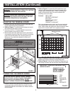
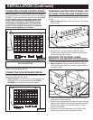
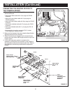
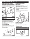
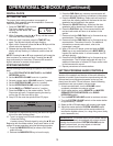
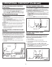
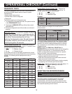
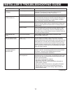
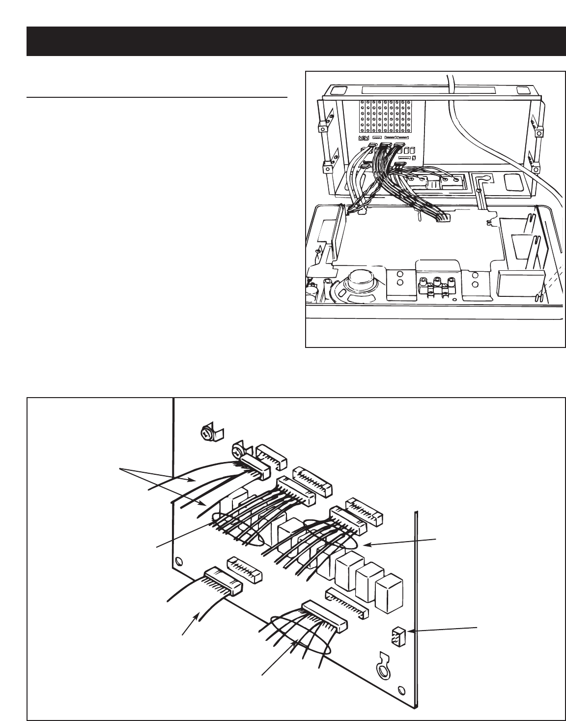
FIGURE 16
FIGURE 17
CONNECTING THE MASTER STATION TO
THE TERMINAL BOARD
1. Refer to Figures 16 and 17. Plug all five connectors into
the terminal board.
1. • Insert black ribbon cable with 10 pin plug into CN104
connector.
1. • Insert multi-color ribbon cable with 14 pin plug into
CN102 connector.
1. • Insert multi-color ribbon cable with 9 pin plug into CN106
connector.
1. • Insert brown shielded cable with 12 pin plug into CN101
connector.
1. • Insert gray shielded cable with 11 pin plug into CN116
connector.
1. • No connection is made to connector CN111 unless
IA-440 expansion module is used.
2. Make sure the alignment keys are properly aligned before
applying pressure to the connector.
3. After all connectors are plugged into the terminal board,
position the extra ribbon cable length toward the top of the
rough-in frame.
4. If an IA-440 expansion module is included in this
installation, proceed with the connection of the module to
the expansion module terminal board at this time. Refer to
the installation instructions provided with the expansion
module.
CN106
CN101
CN116
CN104
CN102
BLACK RIBBON
CABLE WITH
10 PIN PLUG
BROWN CABLE
WITH 12 PIN
PLUG
MULTI-COLOR
RIBBON CABLE
WITH 9 PIN PLUG
GRAY CABLE
WITH 11 PIN
PLUG
CN111
USED WITH
OPTIONAL IA-440
EXPANSION
MODULE
MULTI-COLOR
RIBBON CABLE
WITH 14 PIN
PLUG


