©1997 Numark Industries http://www.numark.com
8
Back Panel Description
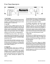
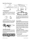
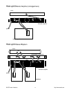
6. Neutrick Connector Inputs
a. Balanced XLR Inputs
These combined inputs are commonly used for both
mobile and installation set ups. The XLR provide a good
combination of ease of connection and resistance to
corrosion. They are wired as per the following
convention:
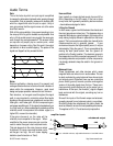
b. Balanced 1/4” Inputs
These types of jacks are featured on many audio
products and are convenient if the amp is frequently
connected and disconnected, such as for a mobile set up.
The plugs used should be wired in the following way:
ring
tip
sleeve
+ -
gnd
7. Balanced Barrier Strip Inputs
These connection points provide the best option for
permanent or long term installation. Connections should
be screwed down tightly to exclude oxygen, and care
should be taken to avoid loose strands of wire that may
cause short circuits.
+ - GND - +
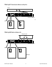
8. Binding Post Outputs
speaker speaker
+
-
BRIDGED MONO
These are suitable for banana plugs, spade lugs or bare
wires. Spade lugs and bare wires should both be
screwed down tightly to exclude oxygen, and care
should be taken to avoid loose strands of wire that may
cause short circuits.
9. Ground Lift Switch
This switch allows the circuit and chassis grounds to be
separated in case of a ground conflict. In normal use the
switch should be in the ‘ground on’ position. Lifting the
ground (‘floating’ position) may resolve the ground
conflict, but means that circuit grounding depends on other
connected components. Deficiencies in the grounding of
other components will affect the sound. A serious electric
fault with the amplifier could damage other components in
the system. For the best combination of safety and
performance it is highly recommended to keep the switch
in the ‘ground on’ position.
10. Stereo / Mono Bridge Switch
In stereo operation, each channel of the amplifier runs
independently with its own signal and speaker(s).
However, both channels can be configured to drive a
single load with a single signal at twice the power.
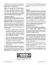
To do this, follow these steps:
1. switch the amp OFF
2. put one speaker of not less than 4 ohms impedance
across the red (+) output terminals of the amplifier


