SMART-V1/SMART-V1G ANTENNA™
This guide provides the basic
information you need to set up
and begin using your new
SMART-V1 or SMART-V1G. For
more detailed information on the
installation and operation of your
receiver, please refer to the
OEMV user manuals. The
manuals and their latest updates
may be found on our website at:
http://www.novatel.com/support/docupdates.htm
SMART-V1/V1G BOX CONTENTS
Accompanying this quick start guide, the following are also
provided with your SMART-V1/V1G:
• 1 CD containing:
• An installation program for NovAtel’s Control and
Display Unit (CDU) graphical user interface software
• Product documentation, including user manuals
• 1 User Manuals postcard for requesting printed manuals
SMART-V1/V1G OPTIONAL CABLES
• The SMART-V1 is availble with a USB, CAN or RS-422
multi-connector cable (these have 7 open ends, see
Table 1, or have no connectors, that is, all open-ended):
• USB (18-pin connector to 2 serial DB-9 connectors,
1 USB connector)
• CAN (18-pin connector to 2 serial DB-9 connectors,
1 CAN DB-9 connector)
• RS-422 (18-pin connector to 3 serial DB-9
connectors)
• The SMART-V1G is available with the USB cable above.
The multi-cables are also available without any
connectors but with all their wires open-ended.
Table 1: Multi-Cables Bare Tagged Wire Colors
ADDITIONAL EQUIPMENT REQUIRED
The additional equipment listed below is required for a basic
setup:
• A Windows-based PC with an RS-232 DB-9 port
• A power supply and connection (+9 to +28 V DC)
• One of the optional cables detailed in the SMART-V1/
V1G Optional Cables section earlier in this guide
SETTING UP YOUR SMART-V1/V1G
Complete the steps below to connect and power your receiver.
1. Mount the SMART-V1/V1G on a secure, stable structure
with an unobstructed view of the sky.
2. Connect the SMART-V1/V1G to a serial port on the PC.
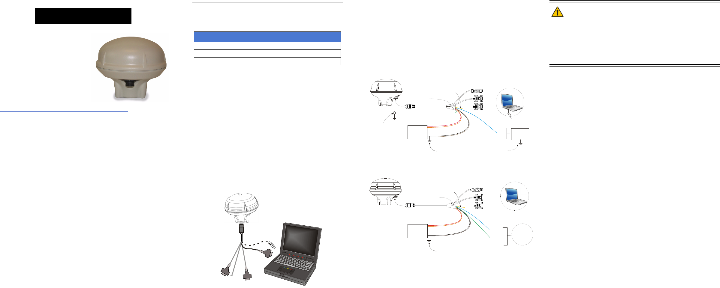
3. When connecting power to the SMART-V1 or SMART-V1G,
it is recommended that you use a battery source. In this
case, it is important that you tie together the bare wires
tagged as GND2 (brown) and GND (black) to the battery’s
negative terminal. Tie the bare wires tagged as PWR (red)
and PWR2 (orange) to the battery’s positive terminal.
Guidelines for grounded and floating installations are shown
in the following diagrams.
WARNING: If you do not use a battery, you must tie together
the bare wires tagged as GND2 (brown), GND
(black) and DIGGND (green) to the DC power
supply’s negative ground connector. Failure to
tie the appropriate grounds, as explained in this
section, may result in your SMART-V1/V1G
becoming permanently damaged and void your
warranty.
Normally when a vehicle engine is started, power can dip to
around 9.6 VDC or even cut-out to ancillary equipment.
INSTALLING THE PC UTILITIES
Once the SMART-V1/V1G is connected to the PC and power
supply, install NovAtel’s PC Utilities
.
1. Start up the PC.
2. Insert the accompanying CD in the CD-ROM drive of the
computer.
3. Select Install the OEMV GPS PC Utilities from the window
that is automatically displayed. If the window does not
automatically open when the CD is inserted, select Run from
the Start menu and select the Browse button to locate
Setup.exe on the CD drive.
4. Install the PC Utilities by advancing through the steps
provided in the NovAtel GPS PC Utilities setup program.
Color Function Color Function
Red PWR Green Digital GND
Orange PWR2 Brown GND2
Blue T SIG (PPS) Black GND
Yellow Reserved
USB o r C AN
to PC
C
O
M
1
C
O
M
2
PWR2 (orange)
GND (black)
USB
COM1
COM2
PPS
(blue)
Digital Ground
(green)
Grounded TE
(Terminal Equipment)
To SMART-V1
Vehicle
Power
Source
This ground may
be inherent
Ground connection
needs to be made
near the antenna to
preclude damage
caused by voltage
differences across
the vehicle chassis
Nearly all vehicles have a
negative chassis ground
PWR (red)
GND2 (brown)
Reserved
(yellow)
COM1, COM2, USB
and Digital Ground
are connected in
cable (where DB9
and USB connectors
are used)
Equipment
interfacing
with PPS
Equipment needs
to be ground-
referenced to use
PPS signal
Chassis Ground Application
PWR2 (orange)
USB
COM1
COM2
PPS (blue)
Floating TE
(Terminal Equipment)
Vehicle
Power
Source
GND (black)
PWR (red)
Reserved
(yellow)
To SMART-V1
Nearly all vehicles have a
negative chassis ground
GND2 (brown)
Floating
equipment
interfacing
with PPS
Digital
Ground
(green)
COM1, COM2,
USB and Digital
Ground are
connected in cable
(where DB9 and
USB connectors
are used)
Floating TE Application


