


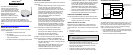
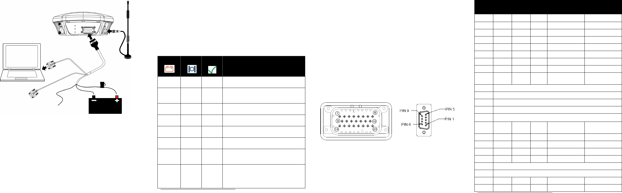
3. Connect the SMART-MR15 to a DB-9 serial port on the
computer.
Figure 2: SMART-MR15 Cabling
4. Provide power to the SMART-MR15, as follows:
Connect the red wire of the cable (PWR+, connector pin 1)
to the positive side of a 12 or 24 V vehicular power circuit (or
equivalent) that is protected by a 5 A fuse. NovAtel
recommends an automotive blade-type fuse, rated for 5 A
and with an operating voltage of more than 36 V
(recommended fuse part numbers are in the SMART-MR10/
15 User Manual).
Connect the black wire of the cable (PWR-, connector pin 9)
to the negative side of the power circuit.
If a NovAtel-supplied SMART-MR15 cable is not used, a
minimum wire size of 0.5 mm/ 20 AWG is required.
5. Connect the cellular antenna to the SMART-MR15.
6. Obtain a valid data SIM and insert into the unit
(GSM/GPRS/HSDPA model only) or activate the product
with Verizon (CDMA model only). Refer to the cellular
activation guide for details.
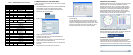
SMART-MR15 LEDS
LEDs on the front of the SMART-MR15 provide basic receiver
status information. The operation of the LEDs on the
SMART-MR15 is summarized in the following table:
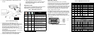
SMART-MR15 CABLES
Cable connectors are illustrated in Figure 3. One DB-9
connector can be used to connect to a computer serial (RS-232)
communication port. The others can be connected to a modem
or radio transmitter to receive differential corrections (refer to
your user-supplied modem or radio transmitter information for its
connectors). In addition, there are a number of bare wires where
the outer insulation is cut away at the ends to expose tinned
wires. Refer to the SMART-MR10/15 User Manual for cable
pinouts. Cables are RoHS compliant.
The SMART-MR15 cable provides a means of receiving power
from a battery. The bare power wires (red for positive and black
for negative) are connected to a battery capable of supplying at
least 5 W. A 5 A fuse must be installed between the positive
terminal of the battery (or power distribution point) and the
positive supply lead of the cable to protect the wiring from short
circuit damage.
Figure 3: 23-pin and DB-9 Connectors
COM1
AUX
Tyco 23-pin
connector
ER
TNC
connector
User supplied
5A fast blow fuse
Cellular antenna
Refer to user manual for
installation guidelines
Table 1: SMART-MR15 LED Behavior
Red
Yellow
Green
Condition
Off Off Off
Power is not available (Red indicator may
also not be lit if a boot failure has occurred).
Flashing
a
a. Flashing means that the LED is turning on and off at a 1 Hz rate - 0.5 seconds on
and 0.5 seconds off.
Any Off
A SIM card error is present or the SIM may
not be installed. Applies only to GSM/
GPRS/HSDPA version of SMART-MR15.
On Off Off
Power available, but no satellites are being
tracked. No cellular network connection.
On Flashing Off
Tracking at least one satellite, but not a valid
position. No cellular network connection.
On On Off
Position valid in basic autonomous mode.
No cellular network connection.
On On Flashing
Connected to cellular network, but not
receiving RTK corrections over NTRIP.
On Flashing Flashing
Tracking at least one satellite, but not a valid
position. Connected to cellular network, but
not receiving RTK corrections over NTRIP.
On On On
The following conditions are true:
• A valid position is available.
• The NTRIP client is in a STREAMING
state.
• An RTK solution is available over NTRIP.
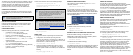
Table 2: SMART-MR15 Evaluation Cable
TYCO
23-pin
COM1 COM2 AUX TINNED LEAD SIGNAL NAME
1 PWR+ (red) PWR+
2 PWR- (black) PWR-
3 CAN- (green) CAN-
4 CAN+ (yellow) CAN+
52 AUXTX
6 3 AUXRX
72 TXD1
82 RTS1
9SIGGND2
(white/black)
SIGGND2
10 RESERVED
11 RESERVED
12 RESERVED
13 RESERVED
14
CHASSIS GROUND
a
a. Pin 14 of the TYCO 23-pin connector is connected to cable shields.
15 5 5 5 SIGGND1
(white/ black)
SIGGND1
16 MKI (white) MKI
17 PPS (orange) PPS
18 ER (blue) ER
19 MODE (violet) MODE
20 RESERVED
21 RESERVED
22 3 CTS1
23 3 RXD1